EDIT: 30/09/2016: There's a new post - Scorbot drawing pictures now. If you like this one follow up to check what it has been doing lately!
About 3 months ago I got this new friend, his name is Scorbot:
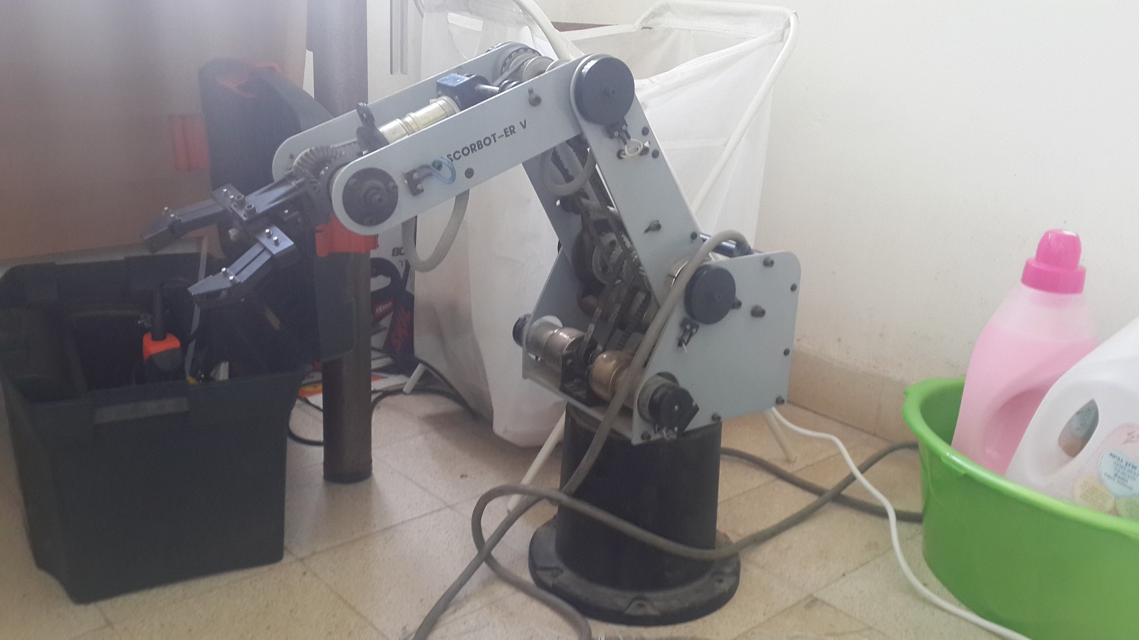
Scorbot was rescued from a junk yard by my friend, bought it for 20USD and brought it to our group for analysis. A quick check on Ebay showed that this type of robotic arm is sold for 300USD minimum! Adding the fact that it was very rusty and filthy and the conclusion was pretty much obvious - Scorbot is probably not gonna work. Well, if I'm writing this post that's probably not what happened.
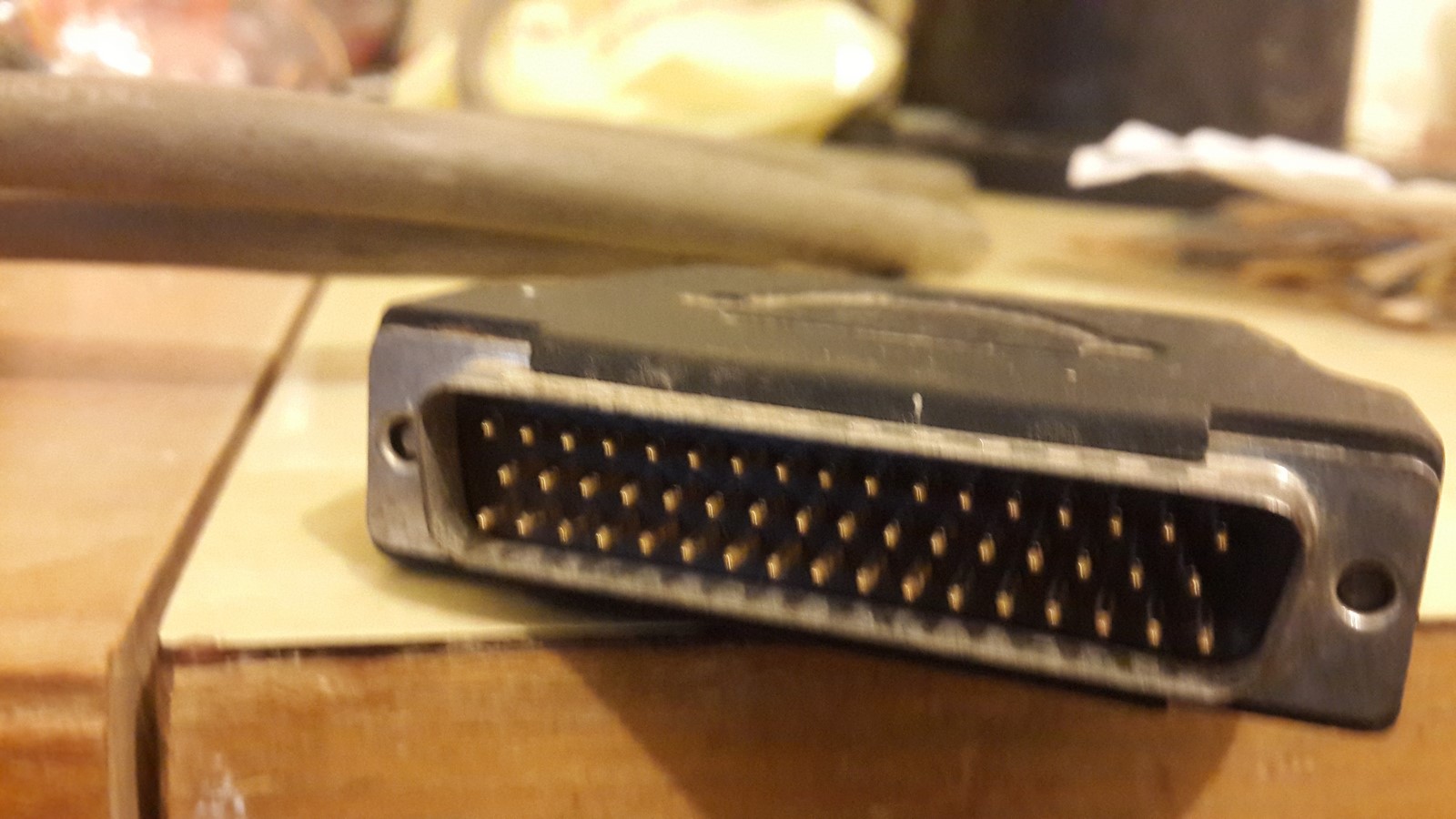
I didn't have any knowledge of robotics, just knew how to connect motor drivers, so I decided it'll be a good opportunity to learn more. On first look I counted 6 motors, each motor had many wires comes out of it and a micro-switch next to it. All the wires were connected through one big cable which ends with a 50 pins connector.
I posted a photo of Scorbot on Facebook and found some replays from friends who studied mechanical engineering in their past. They all recognize scorbot from their university labs, so it was pretty obvious a lot of help can be found over the web. A quick search on google got me Scorbot manual, an older version but still very similar. From the manual it was possible to learn everything you need to know on Scorbot. Indeed, the arm has six motors:
- Motor 1 - Base rotating.
- Motor 2 - Shoulder.
- Motor 3 - Elbow.
- Motor 4+5 when both forward or backward - Gripper pitch.
- Motor 4+5 when one forward or backward and the other is the opposite - Gripper roll.
- Motor 6 - Gripper.
Each motor needs 12V as power and has 2 connections for the motor itself, which is the normal connections of a DC motor. Moving on, it got 4 connection to an optical encoder, which should help counting steps when the motor is working. The optical encoders consist of a led, two photo detectors and encoder disks.
The 50 pins in the connector found to be as in the next table - every three columns consist information of one pin column in the connector, describing the pin number, pin objective and which motor it belongs.
| 1 | P0 | 2 | 34 | P0 | G | |||
| 2 | P0 | 1 | 18 | P0 | 5 | 35 | P0 | 4 |
| 3 | P1 | 5 | 19 | P1 | G | 36 | P0 | 3 |
| 4 | P1 | 3 | 20 | P1 | 4 | 37 | ||
| 5 | P1 | 1 | 21 | P1 | 2 | 38 | ||
| 6 | MS | 5 | 22 | MS | G | 39 | ||
| 7 | MS | 2 | 23 | MS | 1 | 40 | ||
| 8 | MS | 4 | 24 | MS | 3 | 41 | ||
| 9 | LED | 5 | 25 | LED | G | 42 | ||
| 10 | LED | 3 | 26 | LED | 4 | 43 | ||
| 11 | LED | 1 | 27 | LED | 2 | 44 | ||
| 12 | M2 | G | 28 | GND | G | 45 | M1 | G |
| 13 | M2 | 5 | 29 | GND | 5 | 46 | M1 | 5 |
| 14 | M2 | 4 | 30 | GND | 4 | 47 | M1 | 4 |
| 15 | M2 | 3 | 31 | GND | 3 | 48 | M1 | 3 |
| 16 | M2 | 2 | 32 | GND | 2 | 49 | M1 | 2 |
| 17 | M2 | 1 | 33 | GND | 1 | 50 | M1 | 1 |
Notice each motor has two pins for the motor itself, two pins for the encoder's Led and ground and two pins for the photo detectors P0 and P1. Six more pins are connected to the microswitches but in fact there are only 5, the gripper does not have a microswitch but there's a pin kept for that option. Six more pins aren't connected to anything - Not really sure why, perhaps in future version of Scorbot they have a purpose.
Scorbot first steps - Motors
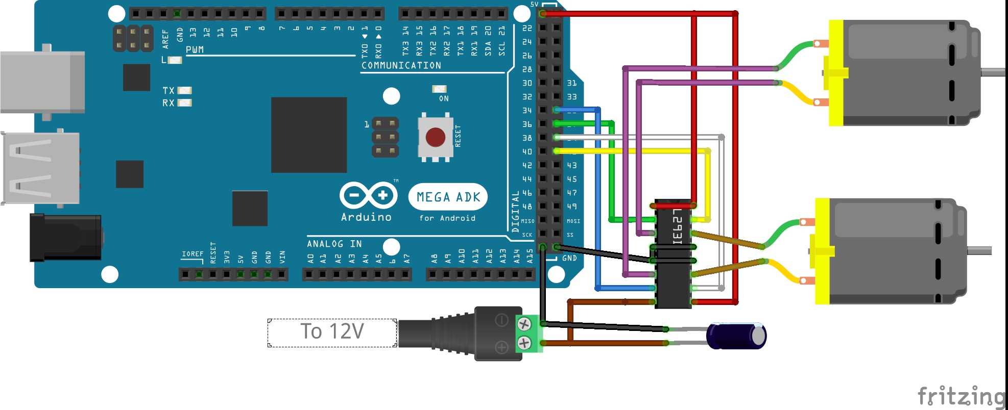
The first step was testing the motors. I plugged 12V to the two pins M1,M2 of each motor and surprisingly all motors were working perfectly! Once I saw all motors were working I was really eager to control the motors with an arduino. I connected all motors with L293D drivers to my arduino MEGA. A sketch of the circle of two of the motors look like this:
Eventually - 3 drivers were needed to control all motors:
Controlling all motors open a path to some cool projects. Notamacuser put a camera on the gripper and made Scorbot to follow faces:
Afterwards, Scorbot came with us to GeekCon where it was really hot so we added another feature to the face tracking - Spraying you with water when you are close enough:
Connecting all pins - Encoders and Microswitches
The next step was to test the rest of the pins. I was still pretty pessimistic that something not gonna work, otherwise why would someone throw it away. Later on I found out that the reason most likely this arm was thrown is because the controller drivers were not updated after windows 98 or 2000 or something like that. The institution owned this arm probably thought it is useless without the controller and bought a new version of Scorbot. That's my guess anyways.
Encoders
Each encoder should be connected as follows:
- Ground pin - Common ground with the rest of the circle.
- LED pin - Connected to 5V with a resistor of ~39Ohm in series. If you don't have 39Ohm it is better to take a bit higher value resistor. If the resistor will be too high the encoder will not work, but if the resistor will be too low the LED will burn and the encoder will NEVER work!
- P0,P1 - These two pins are connected to two digital pins of the arduino. Notice that the arduino pins have to have a pullup resistor otherwise the P0,P1 will not get the "HIGH" value. Fortunately, the arduino has pullup resistor to each one of its pins, they just need to be set at startup using this code:
for (int i=0;i<6;i++) {
pinMode(pin_P0[i],INPUT_PULLUP);
pinMode(pin_P1[i],INPUT_PULLUP);}
In order to read the encoders' values I've used this library. I modified it a bit so it will suit my needs and upload it the my Scorbot repository on github. The (modified) library idea is very simple, it defines one of the timers to be as fast as possible (i.e. no prescaling) and set an interrupt when the timer overflows. For each encoder we define a counter, and when the interrupt is activate (occurs about every ~300ns) it executes a function which checks the 6 encoders P0 and P1 pins and decide whether to add the counter "1","-1" or "0". During the execution of our program we can check the counters and know how many steps a certain motor has moved so far.
Microswitches
Since we don't want to constantly check if a microswitch (MS) is pressed, it should execute an interrupt when pressed. If the interrupt is executed it means the arm-part is at its home position and the encoder counter should be nullified. The arduino MEGA has six pins which can be set as interrupts and this is one of the main reasons why I chose to use it in my project (The UNO has only 2...). In order to connect the MS we first need the ground pin to be connected, same ground as for the encoders. After having the ground pin connected, each MS pin, while pressed, is simply short-circuit into the ground (i.e. set digital "LOW") and just needed to be set to digital "HIGH" while not pressed. In order to do so we can connect the MS pin to one of the arduino pins, passing on the way between two resistors which are connected in series from 5V to ground (Check the next picture if you are confused). I chose the first resistor to be 47KOhm and the second 330KOhm. Doing such, will provide a circuit with almost no current ($\frac{5}{330K+47K} \approx 13uA$ ). When the MS is not pressed, the voltage on the digital pin would be $5\times\frac{330K}{330K+47K} \approx 4.37$ - Still digital "HIGH". When the MS is pressed the pin will be connected to ground and have a "LOW" value. If you familiar with this method you are probably asking yourself why didn't I use here the arduino internal pullup resistor as well as with the encoders. Well, I've tried! The "INPUT_PULLUP" command, when setting a pin as an interrupt, simply didn't work - didn't really bother to check why, if you know let me know!
Summery
To conclude this part, here's an example of how the encoders pins and the microswitches pins should be connected:

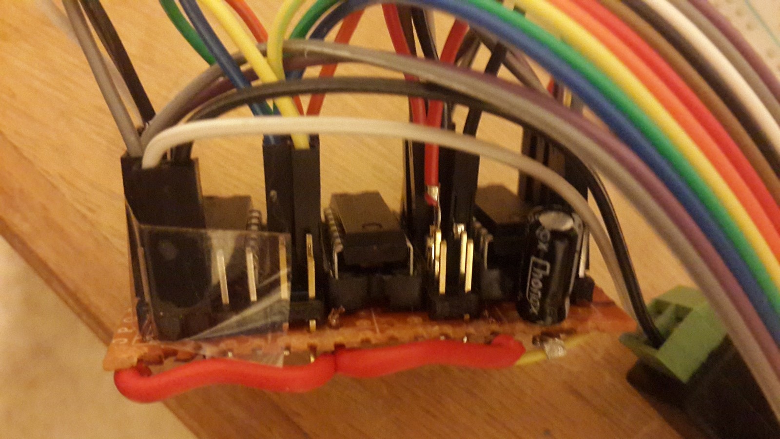
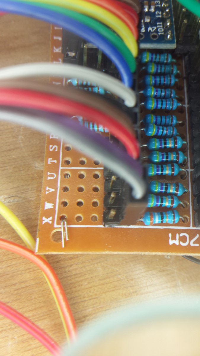
I've soldered all the resistors on one PCB after testing it on a breadboard:
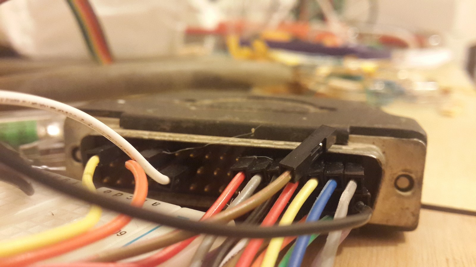
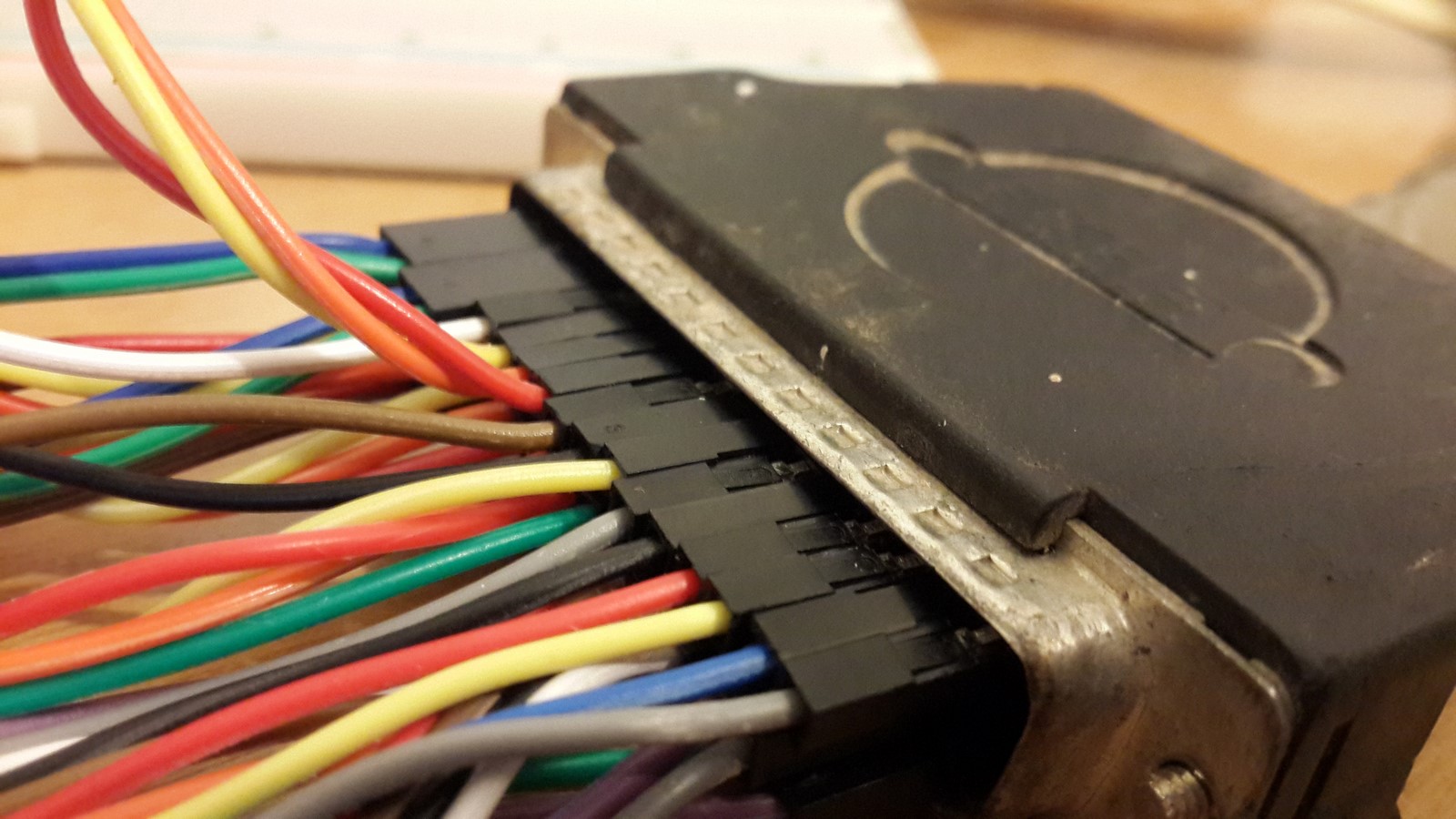
At this point I already connected all the pins, but the 50 pins female connector I ordered from ebay hasn't arrived yet, so it looks something crazy like this:
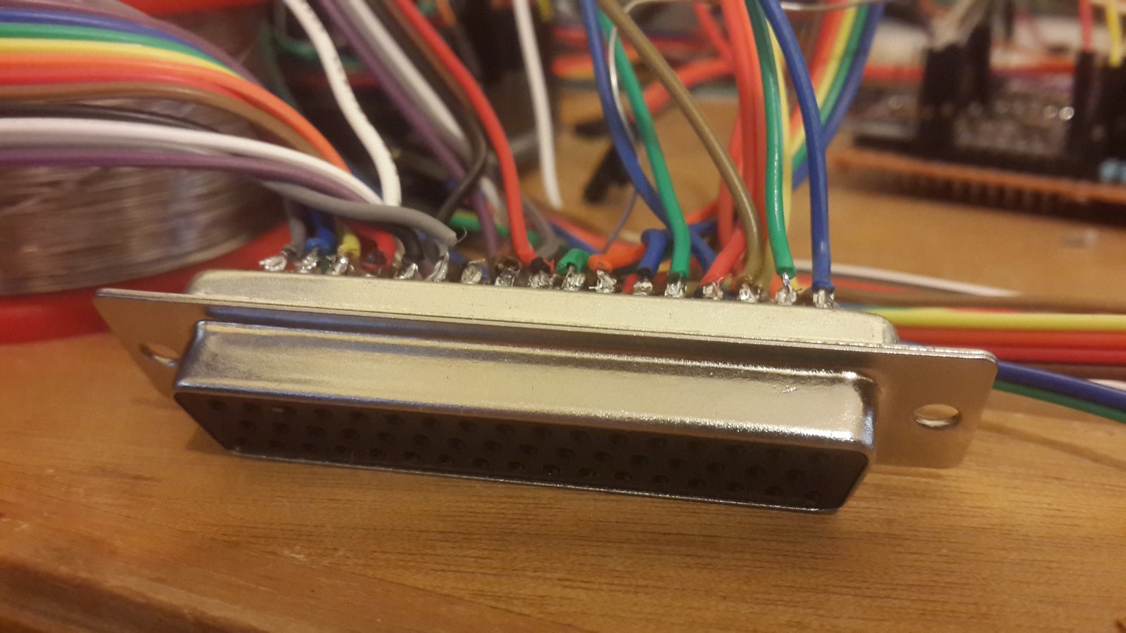
And a few days ago I got the connector so now it looks like this:
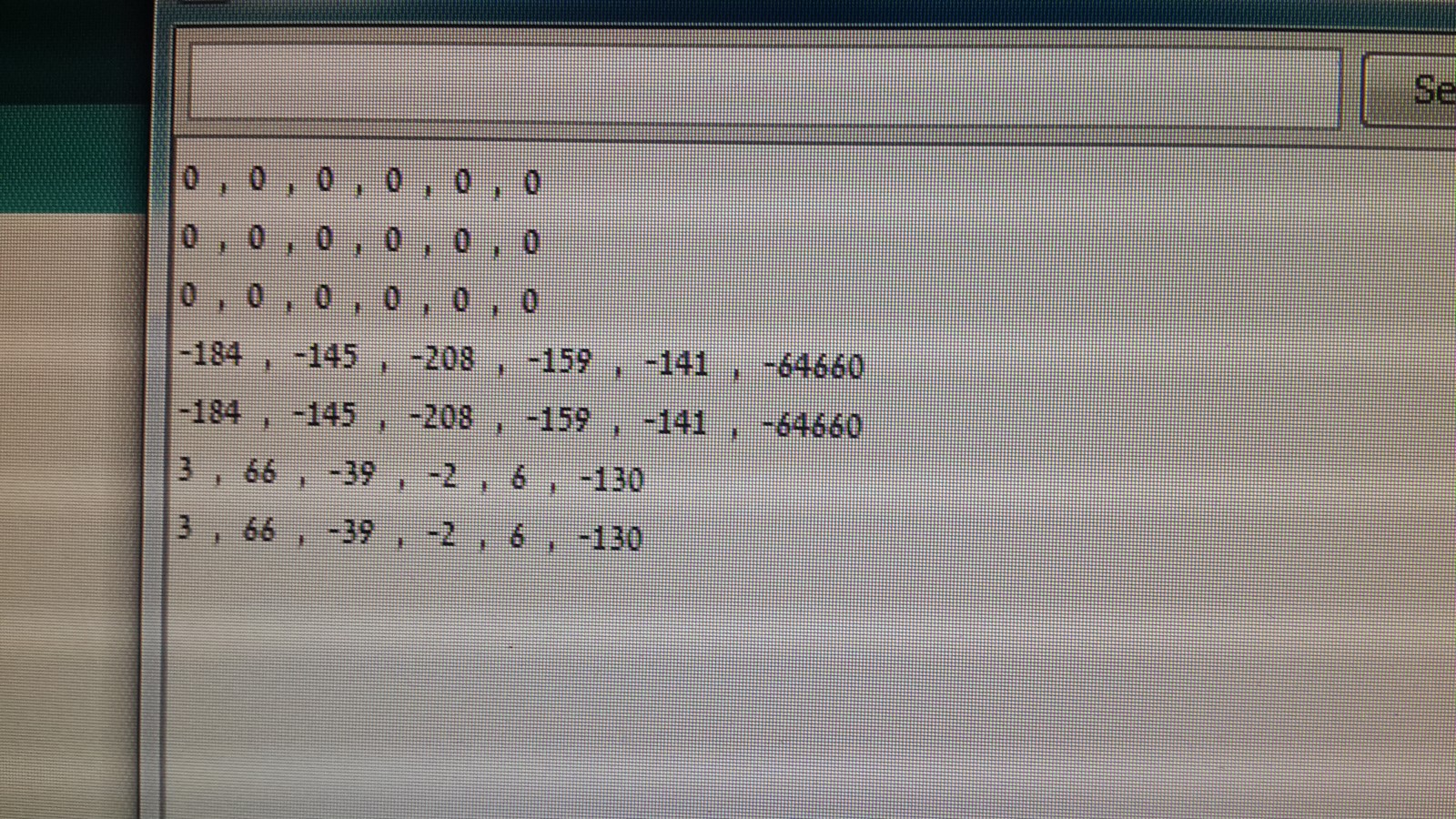
To test this circuit I wrote this code. It simply moves all motors for 500ms and print the encoders' counters so you get something like that:
What next?
This entire post was about bringing back to life a piece of robotic arm with no controller. It took some time but I manage to do it. The next steps are making projects which actually involve a smart control of a robot, which as I said in the beginning I have no knowledge with so far. I've started writing a code which will eventually control Scorbot. The code can be found here and will be updated with time. At the moment it can bring Scorbot back home using the microswitches:
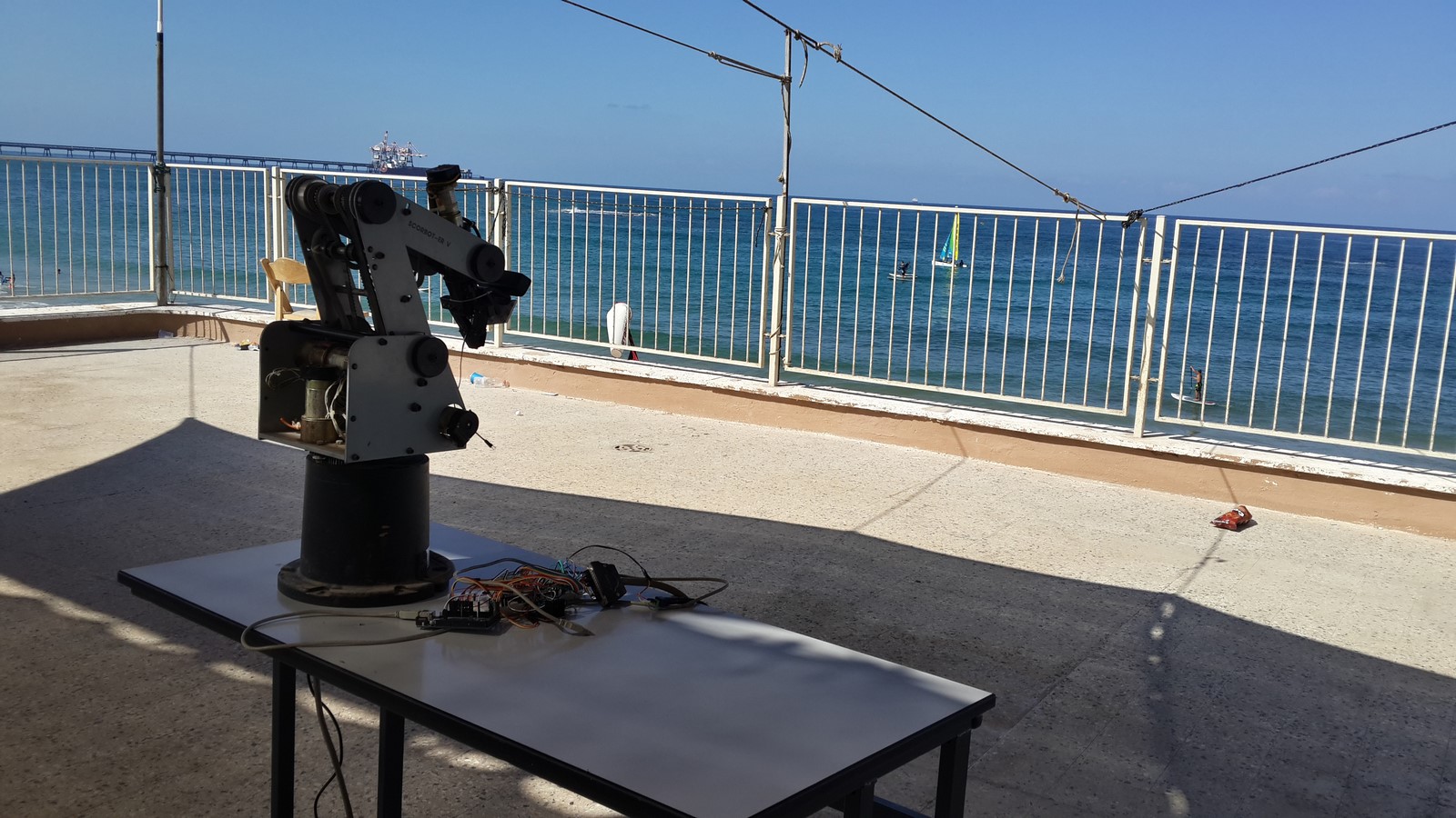
If you have any cool ideas for projects let me know! In the mean time Scorbot is in good hands, likes watching the sea when he is on a break.
AA