The holiday season is near and that means another project with lots of leds :D (Check Last year E-Hanukkiah. I haven't used the ESP8266 for the last six months, and was happy to go back using it, discovering many new libraries which were developed during this time. The last few months I've done a lot! Got married, went for a honeymoon for a month and moved to a new house. The last two weeks I could finally relax and go back to my hobbies. I was doing a lot of houseworks since I moved to the new house, so I decided to combine business with pleasure and created a cool atmosphere lights for my living-room. So what this project consists?
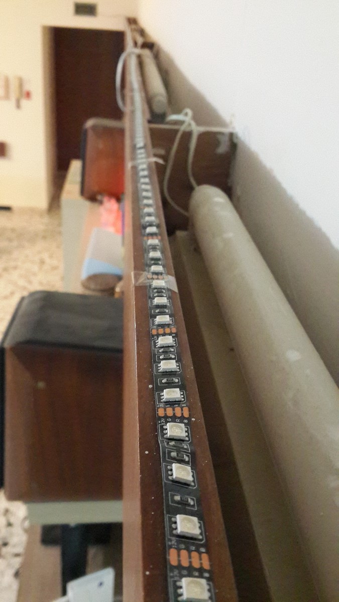
- An ESP8266 which controls a 7 meters, 5050 RGB 12V led strip, 60Leds/meter.
- The ESP8266 is connected to the house router via WiFi.
- The ESP8266 receives data through a websocket on port 81, which means it can be controlled from any browser/OS.
- It supports mdns, so no need for IP address to communicate with the ESP8266 (Partially at the moment).
- It supports OTA (Over-The-Air) updates - So no need to connect it to the computer to update the code.
Here's a video of how it looks like:
The project is more than just leds - It is an robust IOT device sitting in my living-room, listening to different requests. From my point of view, if this project done right, it can lead to several future projects including different sensors which will be connected to the ESP8266, for example: IR sensors to control the TV and AC, Temperature sensors to collect data over time, Smoke detector and more.
In this post I will describe the assembly of this project, but also a lot about the code and problems I encountered on the way.
tl;dr for the ADHD readers: Hope you got this far reading the post, here's my code, go and have fun!
Getting Started
Since the beginning of this project I knew exactly what I wanted to have, but didn't know exactly how will I implement it. The electronics were simple this time, I've already built a led strip controller which reacts to music using an arduino two years ago, so wasn't expecting it to be too different. Sending commands via WiFi to the ESP8266 were pretty simple too - I've done it before via HTTP requests while controlling a water heater or a spectrum analyzer. So basically everything seemed easy but then I wouldn't learn anything new right?
Software
I will write below several subsections on several issues I tried to implement, some succeeded, some succeeded partially, some failed. If it something I didn't used eventually - You can still learn from my mistakes. Also, I'm still working on some of the issues, promise to update if I get more info. If you have any ideas/comments please let me know.
Arduino IDE - Creating A File System.
Programming the ESP8266 using the Arduino IDE is a great and simple way to create your own code. I find it much better than using The nodeMCU Firmware, especially for real-time projects. LUA (NodeMCU language) is a scripting language, much slower than C++ code (Arduino IDE language). While so, I found LUA to be much easier for implementing fast and more complex ideas such as handling files and such. So, it seems that nodeMCU is more suitable to simple IOT projects while writing code with the arduino IDE is better for real-time and more uncommon projects.
After understanding all of this, it was just a matter of time someone will write a C++ file-system library for the ESP8266, after all the module has a relatively-large flash memory so it was expected.
Why was I looking for this library? I thought the best way to start this project is to create a nice interactive HTML web page on the ESP8266 server, which will be sent upon request from the client and will hold a nice GUI to control the leds.
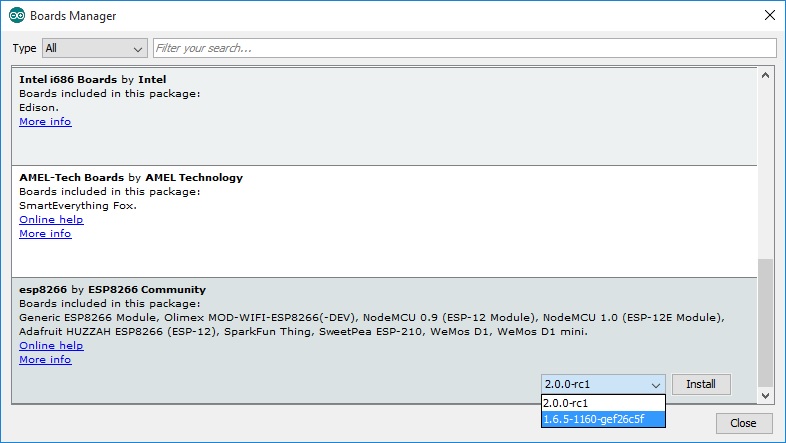
As for last week, the FS library is part of the stable version of the arduino IDE (2.0.0). In order to use it before last week, and also in general if you want to change the libraries from the stable version to the development version you should go to File--> Preferences --> Additional Boards Manager URLS, and change the path from http://arduino.esp8266.com/stable/package_esp8266com_index.json to http://arduino.esp8266.com/staging/package_esp8266com_index.json. Then go to Tools--> Boards --> Boards Manager, and choose the version of ESP8266 code you want as shown here:
 From here it should be simple.
- Press Ctrl+K to go to your sketch library.
- Open a new folder name "Data".
- Copy the HTML/JSON/CSS files to this folder.
- Go to Tools --> ESP8266 Sketch Data Upload and the files will be uploaded to the flash memory (Assuming you selected the right ESP8266 board).
After the files are there, you can keep writing your code, include the FS library (#include "FS.h") and just read about its functions and use it.
Unfortunately, I don't have a code example since I ended up not using it. I decided to go with a different approach which didn't need the files to be on the ESP8266. The approach included websockets which will be described in the next subsection.
Websockets - Sending and Receiving Data
Up until now I was using HTTP requests to send and receive data to and from the ESP8266. For this project, since I decided not using the file system library, I wanted to open a TCP connection with the ESP8266 and transfer data continuously. I thought about creating my own protocol for the TCP connection, but then I found out about the websocket library for ESP8266, mainly through this project by Rahul27 which is basically a proof-of-concept of what I planned to do. The websocket is a protocol running over TCP, it has very low latency (~2ms) and easy to use. When using a websocket you don't need to care about the length of your data, and also about it's type. I start playing with Rahul27 code and it wasn't long before it became the basics to my code (Thanks Rahul27!).
Some explanations on how to implement the websocket code:
On the ESP8266 side:
Long Side-Note: While using this code I encountered a problem which made the websocket disconnect. Digging in a bit I realize it happens when the ESP8266 tries to send data but its "receiving buffer" is not empty yet (meaning it still receives data). Both sending and receiving shouldn't interfare with eachother because of the RX/TX system, but it could be that while I was receiving a lot of data I was also sending a lot of data and then the "sending buffer" was full causing the websocket to disconnect. I still don't know what is the right way to fix it - but if it happens to you as well I partially solved it by not sending any data while the buffer is not yet empty. To do so you have to open the WebSocketServer.cpp, go to the WebSocketsServer::sendTXT function and just before the sendFrame line, add this code:
        if(client->tcp.available() > 0) {
            DEBUG_WEBSOCKETS("[WS-Server][%d][handleHeader] SEND: Buffer is not empty, cancelling respond");
            return;
        }
And that will create some delay which mostly ensure the "sending buffer" will not become full.
- To use the websocket as server you'll need to include the library
#include <WebSocketsServer.h> - Create a websocket variable and choose its port:
WebSocketsServer webSocket = WebSocketsServer(81); - On the
setup()function you need to add this code:
  webSocket.begin();
  webSocket.onEvent(webSocketEvent);
Which will begin listening and when it will receive data will go to webSocketEvent function.
- On the
loop()function you should addwebSocket.loop(); - Last, you have to define the
webSocketEventfunction that will interpret the received data:
void webSocketEvent(uint8_t num, WStype_t type, uint8_t * payload, size_t length) {
  switch (type) {
    case WStype_DISCONNECTED:
    case WStype_CONNECTED:
    case WStype_TEXT:
    case WStype_BIN:
    }
}
Under the case of WStype_TEXT you can add all the code you want to execute while sending text strings to the ESP8266.
On the browser side:
- Open a connection using this script and the correct IP (Using JavaScript):
var text = document.getElementById('ip').value;
ipValue = text;
connection = new WebSocket(ipValue, ['arduino']);
- Send a string using this code:
connection.send("STRING");
Note: I've notice this code is working fine on Chrome and Internet Explorer. On Edge (The new Microsoft browser) it didn't work. According to Wikipedia:
A secure version of the WebSocket protocol is implemented in Firefox 6, Safari 6, Google Chrome 14, Opera 12.10 and Internet Explorer 10.
As you see, this is a very simple way to pass big amount of data in real-time to and from the ESP8266.
Back to the code - I've built a webpage and put it on one of my servers so I could access it from any computer. I've built it using RIB, a cool open source GUI for building the basics of nice web-pages. Then, I've added the JavaScript functions which open websocket and send the data. For the moment it looks like that:
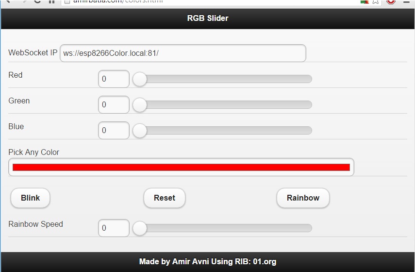
What can be seen on this page:
- First line - Choosing the websocket IP/HostName and port (This is not the last websocket I'm gonna use :D ).
- Three sliders for red, green and blue with values 0-1023. Playing with any of these sliders sends a command to the ESP8266 with the color and value.
- "Pick Any Color" - Using HTML5 you can open a color pallet, choose any color and the RGB sequence is sent to the ESP8266
- Buttons for
- Blink for one second (Good for testing)
- Reset - Turn off light.
- Rainbow - Start a sequence of changing the colors on a color wheel
- Rainbow slider - Sends the ESP8266 a command for the speed of the changing colors.
If we go to "Inspect elements" on Chrome we can debug the script and see that the websocket is open and sending data to the ESP8266. Notice that each data string can have a different length, the length is part of the sent data.
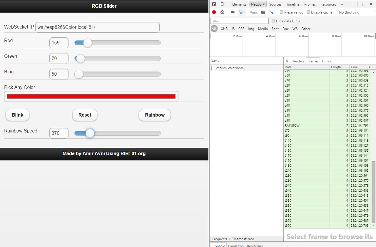
On the ESP8266 side, as explained before, the code detects the received string under the case of WStype_TEXT and use the analogWrite() to change the PWM duty-cycle on the pin which controls a certain color (More about the hardware later in this post).
MDNS
MDNS, or Multicast DNS, is an easy way to communicate with the ESP8266, using a constant hostname instead of an IP address (Which is not constant unless you use static IP). The last version of the arduino IDE supports mdns, mdns however, is not so simple to use.
Lets start with the code - In order to define a hostname for your ESP8266:
- Include the mdns library:
#include <ESP8266mDNS.h> - On
setup(), setup the mdns service.
void MDNSConnect() {
  if (!MDNS.begin("YourHostName")) {
   DEBUGGING("Error setting up MDNS responder!");
    while (1) {
      delay(1000);
    }
  }
  DEBUGGING("mDNS responder started");
  MDNS.addService("ws", "tcp", 81);
  MDNS.addService("http", "tcp", 80);
}
Note that in my project I had two TCP listening ports, one for websocket and one for HTTP, so I've added mdns service for each one of those sockets.
Next step is to install on your computer a service which resolves mdns requests. Bonjour is a service like that, by Apple but can be installed on windows as well (Just don't be tempted to install iTunes when it ask you to :P ).
After Installing Bonjour, you can go to your browser and type YourHostName.local and the browser will know to which IP address it should aim the HTTP/WS requests. If you check once again the picture of the web page I've added before, you will see the websocket has a hostname and no IP address.
The problem starts when you are using more than one computer to send messages to the ESP8266. In this case you can either install Bonjour on all computers, or you have to config your router such that it will know to resolve hostnames not only through dns servers over the internet but also through the computer with Bonjour service. Apple routers support Bonjour naturally since other Apple products use this service. In my case I could not config my own router to support it at the moment, still working on it.
Over-The-Air(OTA) Code Updates
Another cool library I've learned about through this project, is the ESP8266HTTPUpdateServer which creates a HTTP server on the ESP8266, where you can upload a binary firmware file via WiFi and it will be flashed on the micro-controller. This basically means that you can update your code
"over the air".
How to implement? On the ESP8266 side:
- Include the libraries
#include <ESP8266HTTPUpdateServer.h>, and#include <ESP8266WebServer.h> - Create a webserver varible
ESP8266WebServer httpServer(80); - Create an "Update Server" variable
ESP8266HTTPUpdateServer httpUpdater; - On
setup(), setup and start the service
void HTTPUpdateConnect() {
  httpUpdater.setup(&httpServer);
  httpServer.begin();
}
Now, when you type in your browser the hostname/IP and add /update you will get this window:
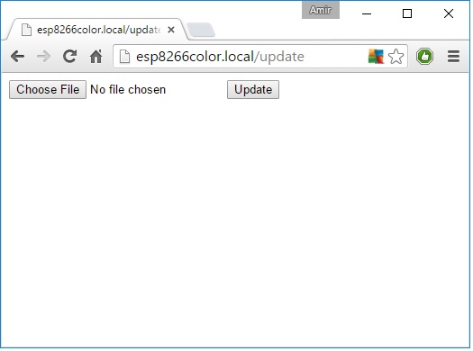
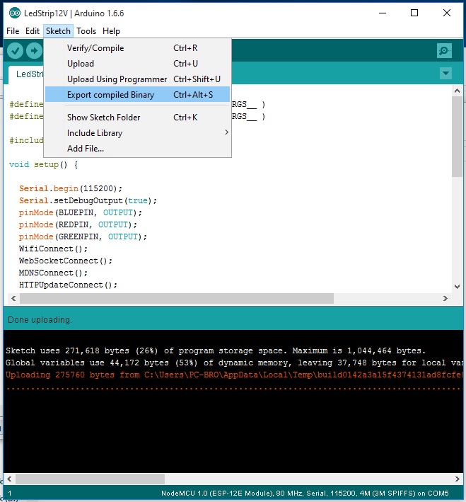
In order to upload a new code, you'll first have to compile it to a binary file. You can do this by pressing Ctrl+Alt+S in your IDE window, or simply go to Sketch--> Export Compiled binary:
The binary file will be saved in your sketch folder, and all you have to do now is choose it on the web page and press Update. Next, the following steps will happen (described nicely also here):
- The binary code is uploaded to the ESP8266 and is saved on the flash memory.
- The ESP8266 reset itself, starts in flashing mode.
- The ESP8266 start flashing the new firmware from the flash memory.
- When done, the ESP8266 reset itself and run the new code.
Pretty cool feature! But still few notes should be considered when using this feature:
- Do not delete/tamper the part of the code of the OTA updates. If you do so, you will not be able to use the OTA updates anymore and have to connect the ESP8266 to the computer the next time you want to upload new code.
- The ESP8266 module should support resetting and booting automatically in flashing mode. The NodeMCU does that but simple boards like the ESP-12 doesn't do that. When using the ESP-12 you'll have to add a flashing button which connects GPIO0 to GND when pressed, and keep it pressed while uploading new firmware.
- Security - Everyone who has access to the ESP8266 server can upload a file. This upload should be protected with password or other measures - This is a future project I think about these days :D.
The Rest of My Code
Up until now in this section I explained a bit about websocket, MDNS and OTA. Other than that, my code is pretty simple and can be found here.
The setup() function does the following:
- Define RGB pins as outputs.
- Connect to WiFi.
- Begin websocket.
- Begin mdns service.
- Begin OTA service.
The loop() function repeat the next functions:
- Listening to a websocket, react when response is needed.
- Listening to an HTTP server, react when response is needed.
- If enough time has passed and the rainbow flag is on, change the color of the leds using the
wheel()function which gets an integer and return the next RGB color on a HUE wheel.
Also, commenting/uncommenting the first two lines in the code will control disabling/enabling debugging/print to serial options.
#define DEBUGGING(...) Serial.println( __VA_ARGS__ )
#define DEBUGGING_L(...) Serial.print( __VA_ARGS__ )
Hardware
After understing the software part we can move to the hardware part which is a whole different story with different problems and different solutions.
I've already written this post on how to drive a led strip using the arduino pins. In this project the idea was pretty similar but with a few changes:
- The ESP8266 pin-out can deliver less current than the arduino pin-out (around 10-15mA).
- The led strip was about seven meters long, with about 450 RGB 5050 leds, which means much more current needed to be driven to the strip (~8A)
This is the sketch of how the control circuit should look like:
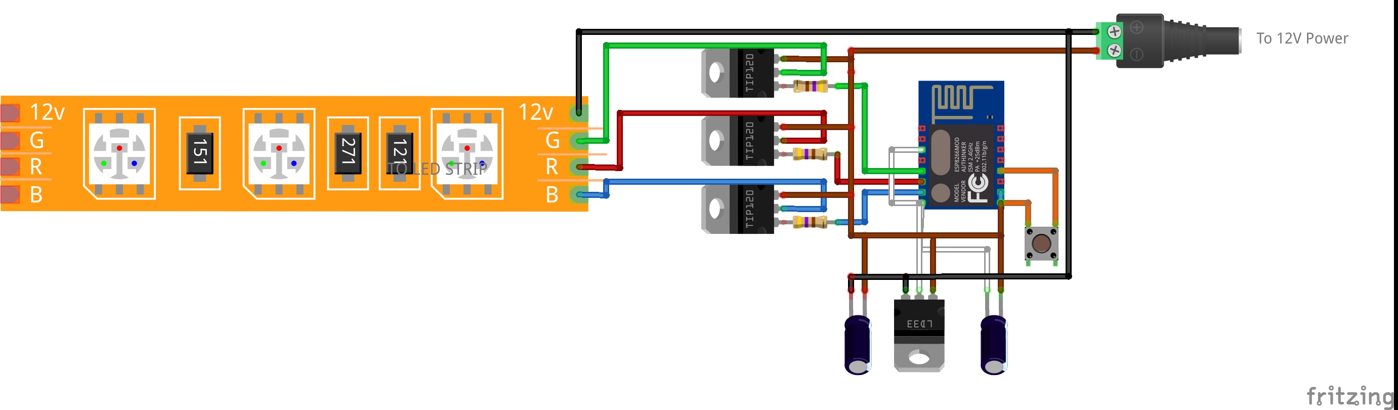
The main difference from the arduino project is that I've used TIP122 NPN darlingtons instead of the TIP31 NPN transistors. The explanation is pretty simple, each transistor has h_fe value which roughly means the current gain it can give or the ratio between the current which will flow on the NPN base to the current on the NPN collector. So if we check the TIP31 datasheet, we will see its max gain is 50. Assuming the ESP8266 can deliver 15mA, the current it can drive will be $15\cdot50 = 750mA$, which is not nearly enough to the current we need for the led strip. A darlington on the other hand can be explained as two NPN transistors connected together

So its gain will be much higher. Checking the TIP122 datasheet we can see that its h_fe is about 1000, which means that output of 15mA can drive 15A of current, which is more than enough for this project.
Another related issue is the power supply. The led strip needs 12V, so the power supply should support this voltage, not higher or you'll burn the leds, but it also needs to support the current needed to be driven.
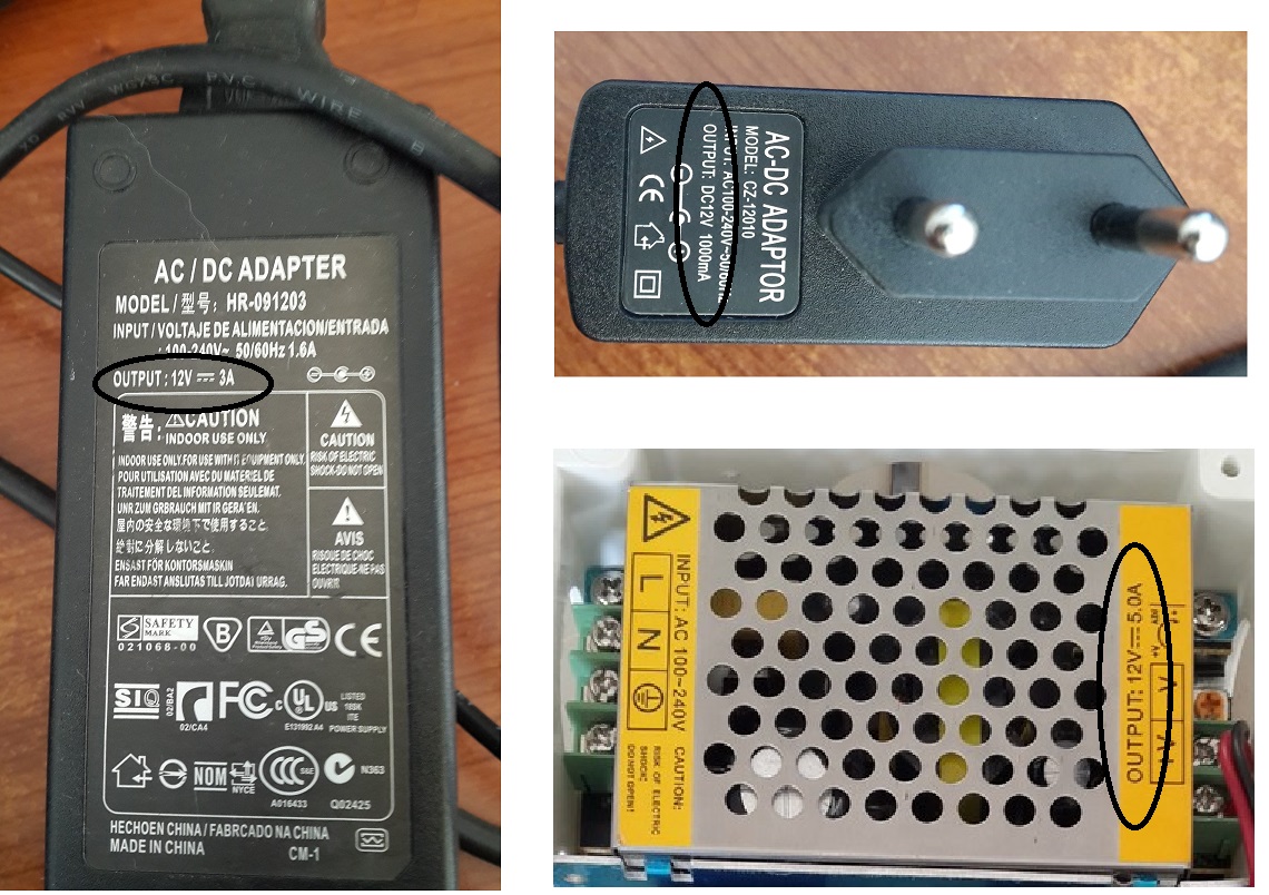
I've used the 5A power supply, which do not give full brightness to the led strip but was enough for what I needed.
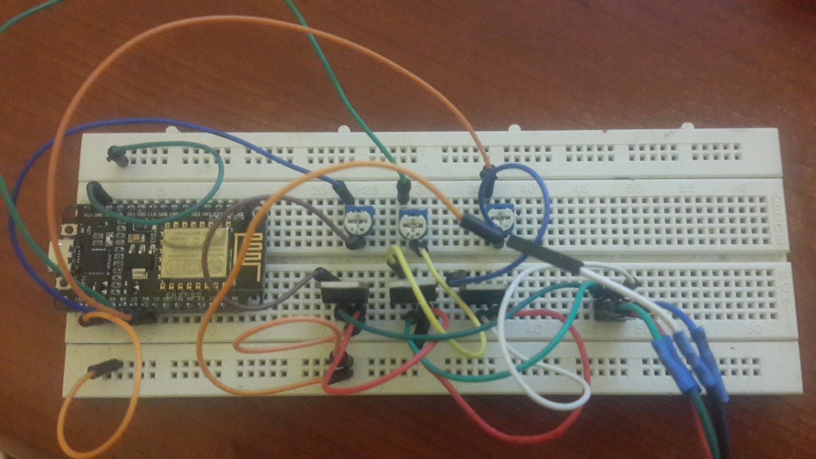
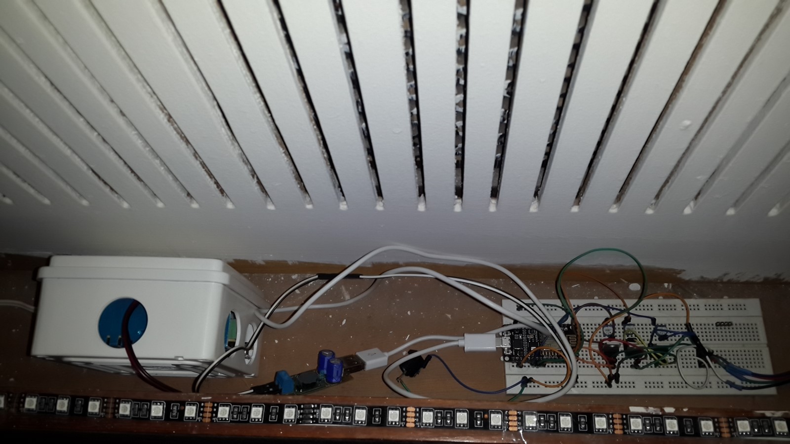
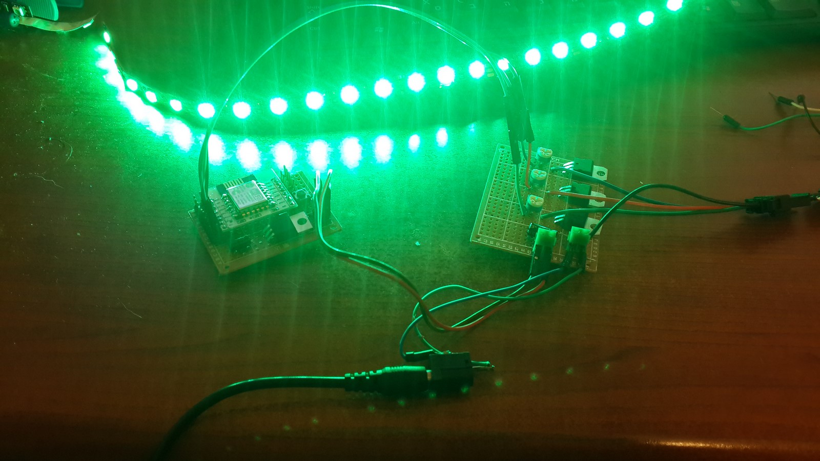
In order to make sure the code works, I started by connecting everything on a breadboard
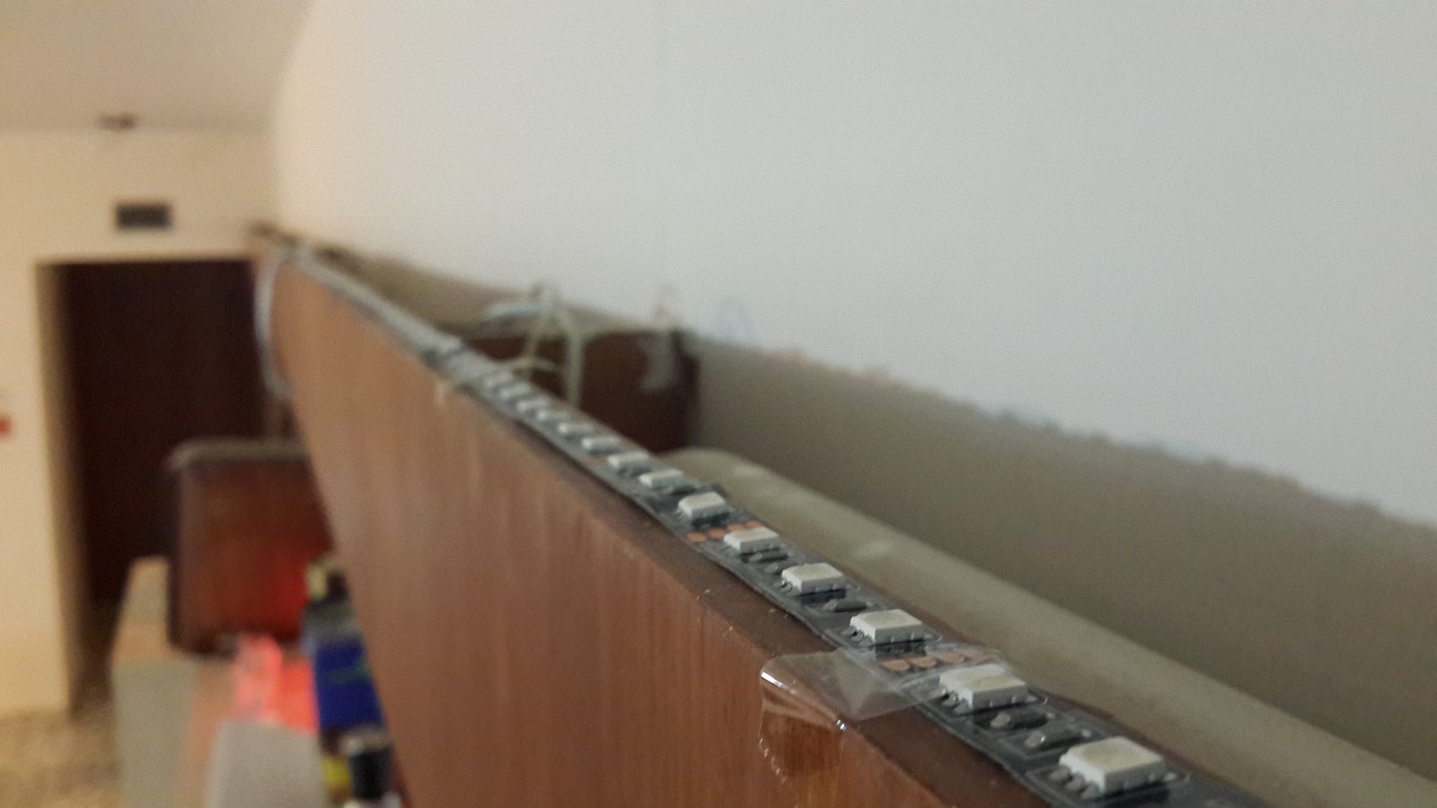
When the code was ready I mounted the led strip to where it should be, only with duct-tape, just for first shot - if it wasn't so nice why should I keep bothering? (It was nice though!)
Then I connected the power supply and the ESP8266 circuit and test it. Make sure you have a power supply which connects to an outlet, otherwise if you are not professional and familiar with the safety measures you should call someone who does.
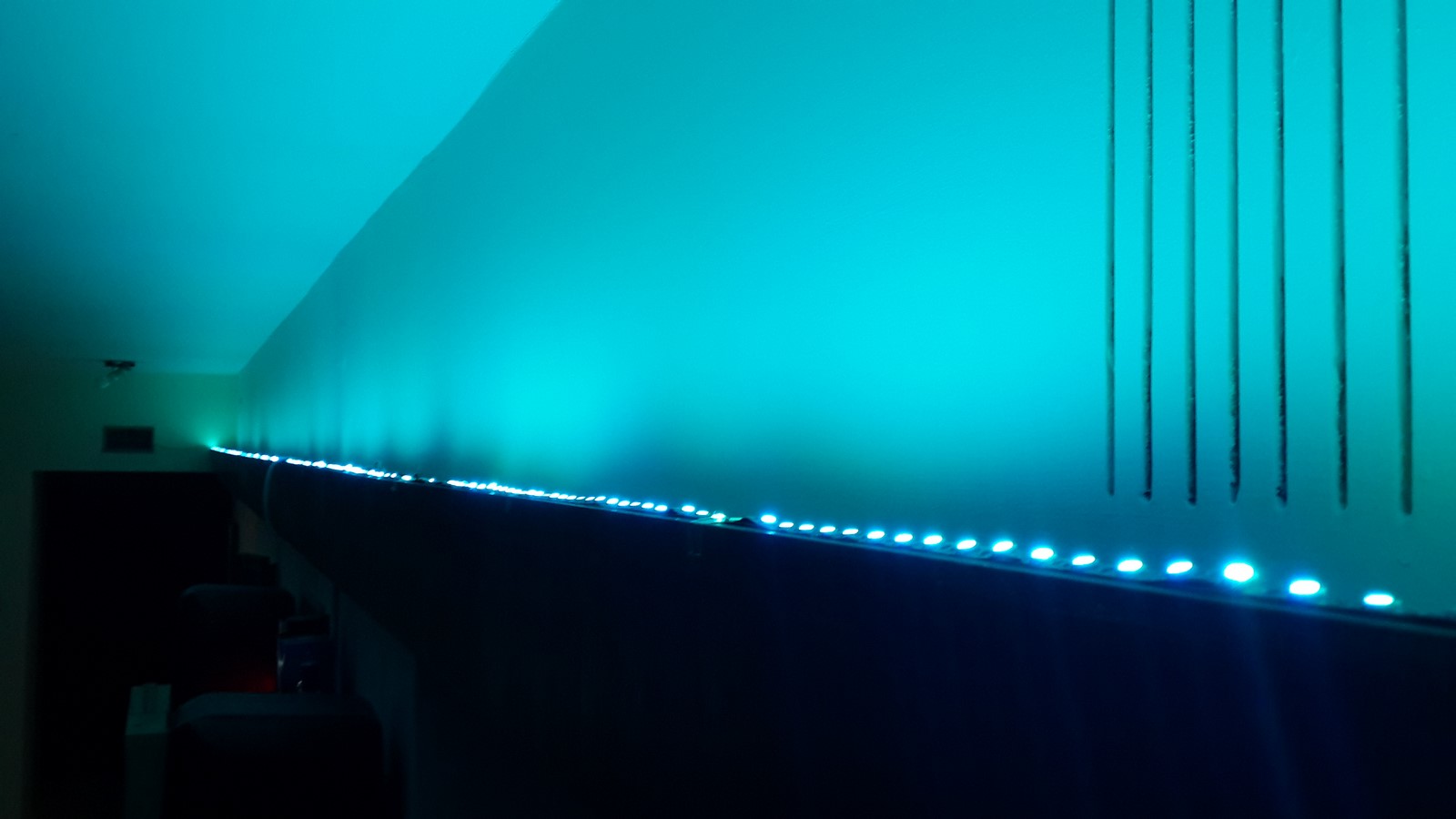
The first impression was very nice
On hindsight, it wasn't such a good idea. I immediately noticed the leds do not work on their full brightness. So I decided to check the current flows to the leds.
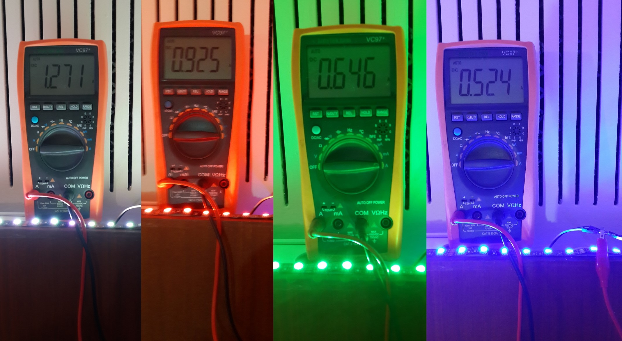
It seems as the current was much lower than expected, and didn't sum up when I turned on each of the RGB leds and all of them together (white color). The reason was pretty obvious - It was the use of cheap jumper wires which could not handle this current. Immediately I noticed the cables were pretty hot and the breadboard started melting a bit .
So the next move was to replace the led strip wires to thicker ones and not use them on the bread board. Also, I should have known but I noticed that the overall voltage from the power supply is 12V but the overall voltage on the leds was lower - This is since some of the voltage drops on the TIP122 transistors. So after these changes I tested the strip again
This time the current was 3A and the leds were brighter. This was still less current than I expected to get but I thought at the time that this is the max I can get due to the resistance of the long (and cheap made) strip.
OK, I loved what I've seen, my wife loved it as well, so I moved on to make the circuit more robust.
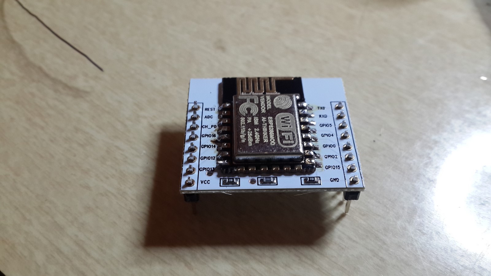
Since the nodeMCU board is a development and more expensive board, I switched to an ESP-12e module, and soldered it on a board which makes it easier to be handled.
Then I made two boards, one for the led strip driver and one for the ESP
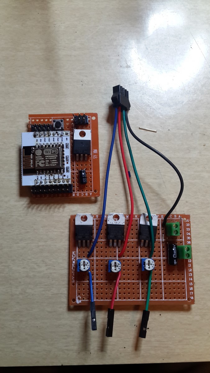
Why not one board? As I explained before, I believe I will use this ESP8266 for more future projects such that their will be more boards connected to this module, so I decided to divide between those two circuits. Note that in past projects I've used the LM1117 voltage regulator to drop 5V voltage to 3.3V voltage. The same product can be used here as well to drop 12V to 3.3V.
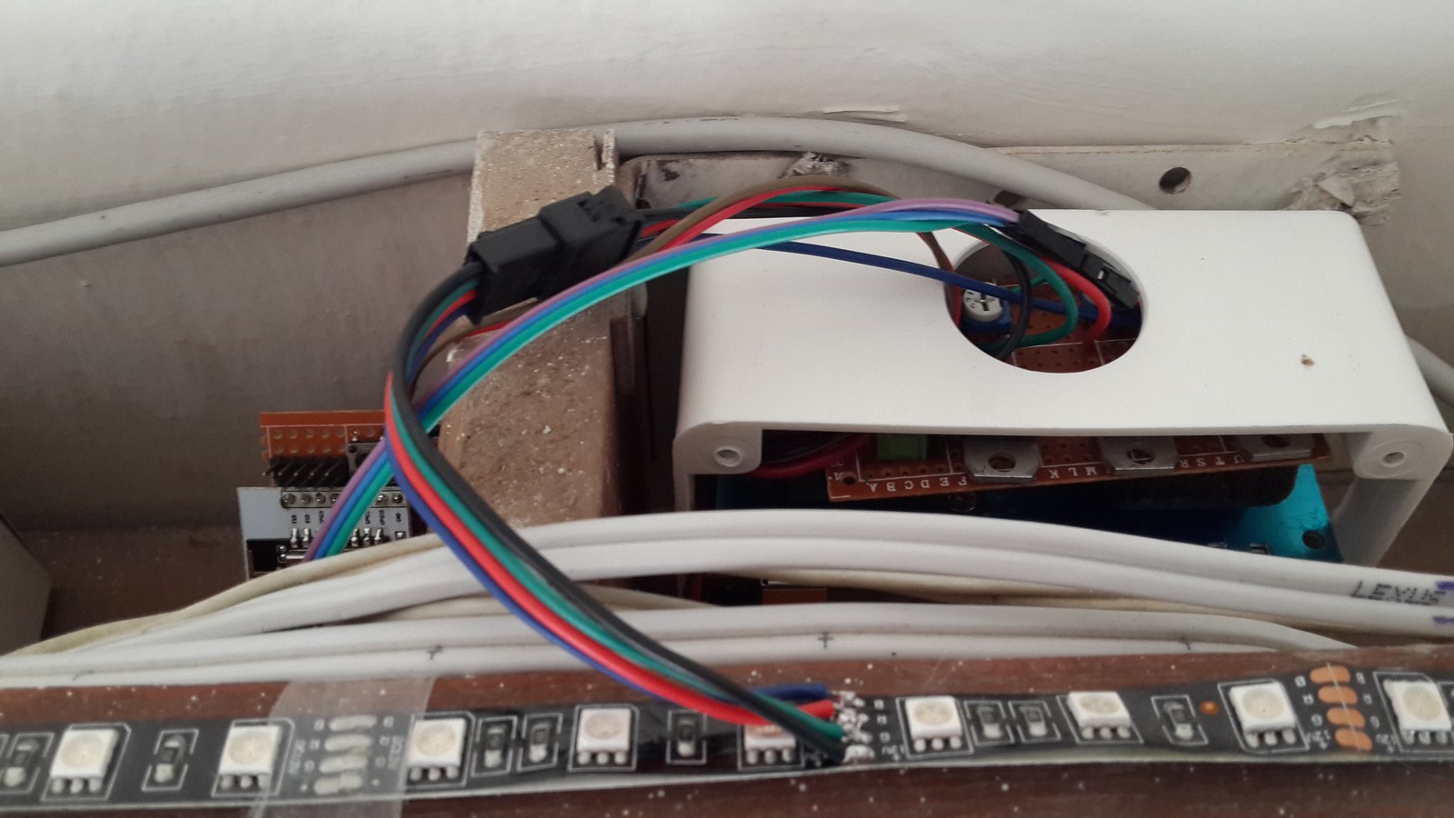
First I tested the boards before fixing them on the wall. Note that the jumper wires connected between the two boards are still thin, since the high current do not flow through them.
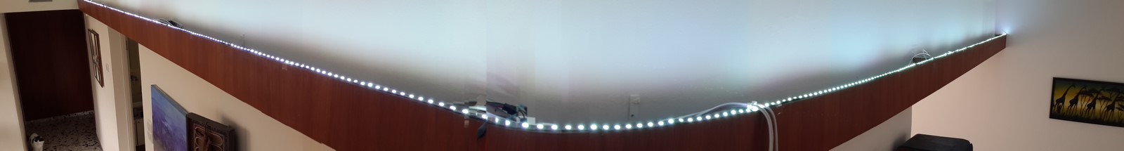
I put everything on the wall
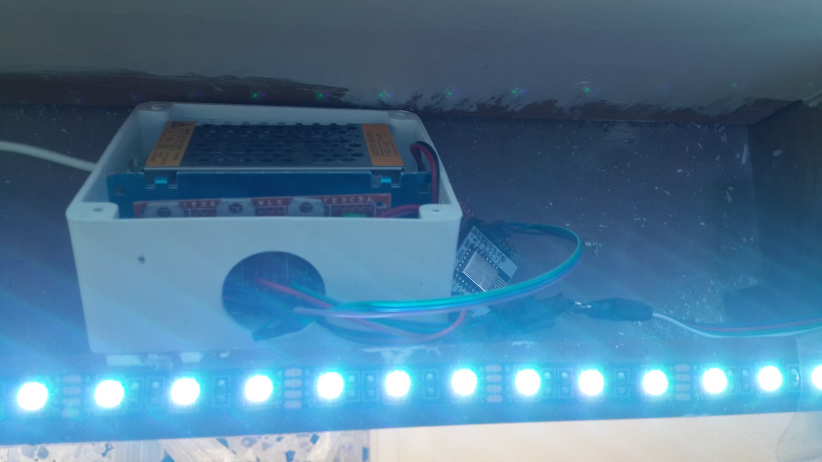
I also decided to power the leds from the middle of the strip and not from the side, was wondering if the resistance will be lower.
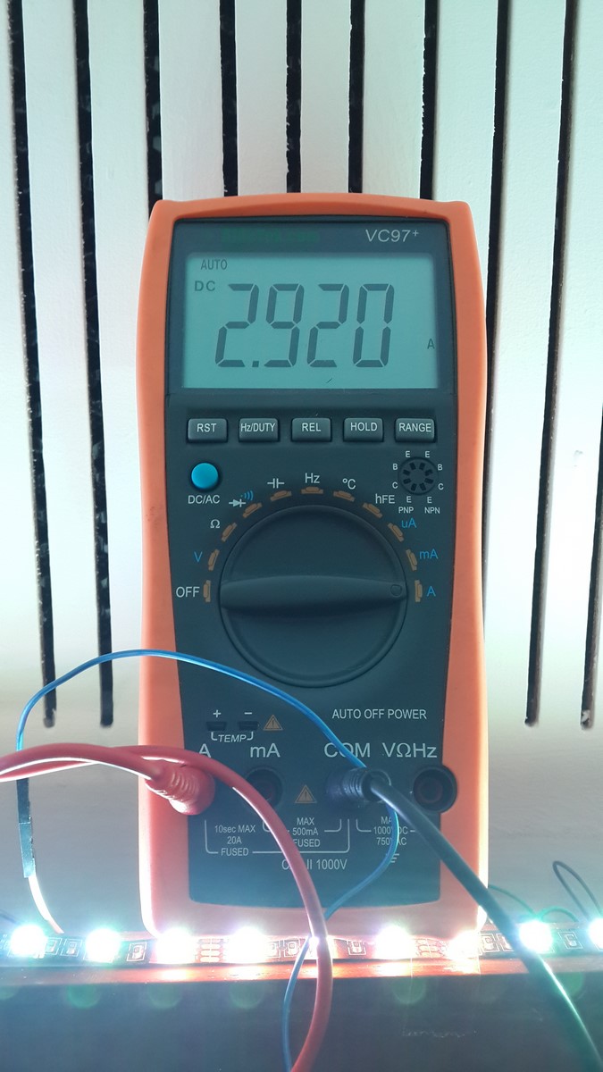
Then something unexpected happened - after about a minute of the brightest white color the leds turned off. I turned everything off and on again and once again after one minute everything turned off. I noticed the entire box was very hot and decided to test the current once again, then I was pretty shocked!
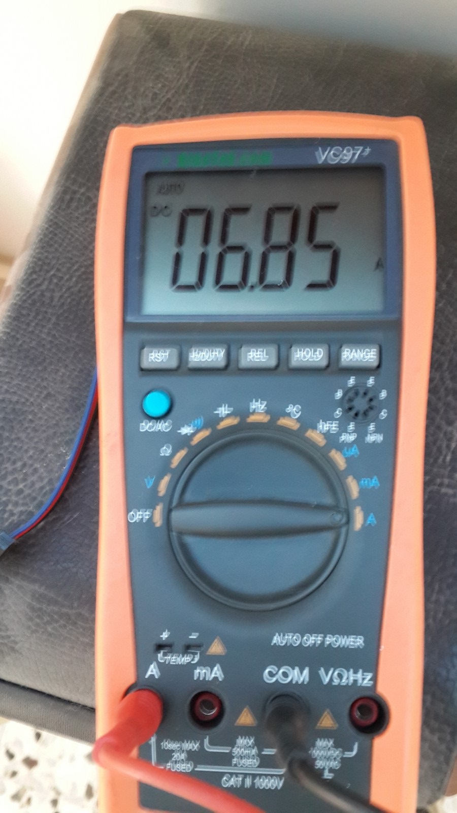
The current was almost 7A!! (I was so shcocked that the picture turned out blurry :D ). I DID expect it from the math I made but didn't think it will actually go to these values. I was lucky that the power supply, which can supply max 5A according to its specs, had some defense mechanisms which unplugged it when it got too hot. I quickly adjusted the power supply voltage such that the highest current will get to 4.9A, a bit less then 5A just to be safe. The brightness stayed almost the same so it didn't really bothered me.
When everything was done, I removed the duct-tape from the led strip, mounted it in a better way to the wall, filmed the video from the beginning of the post and enjoyed the new atmosphere.
Hope you enjoyed reading about this project, and that you won't do the mistakes I've made. Any questions, ideas for improvements or comments? Please comment below.
AA
Edit: (March 6 2016) -
The user "Alex" has used this code and improved it, added some features which update the webpage back according to the ESP8266 state. You can check the comment section for the entire discussion and his code here:
https://github.com/TheAustrian/ESP8266-LED-Websockets