It has been quite a long time since I have written a post on this blog. The main reason is the free time I have, or haven't, since my baby daughter was born 9 months ago.
Nevertheless I keep making fun project, just have less time to document them - But I keep taking photos and videos of everything I do so eventually it WILL be documented here on the blog.
Intro
So lets talk about a really short and easy project - two hours max - I guarantee!
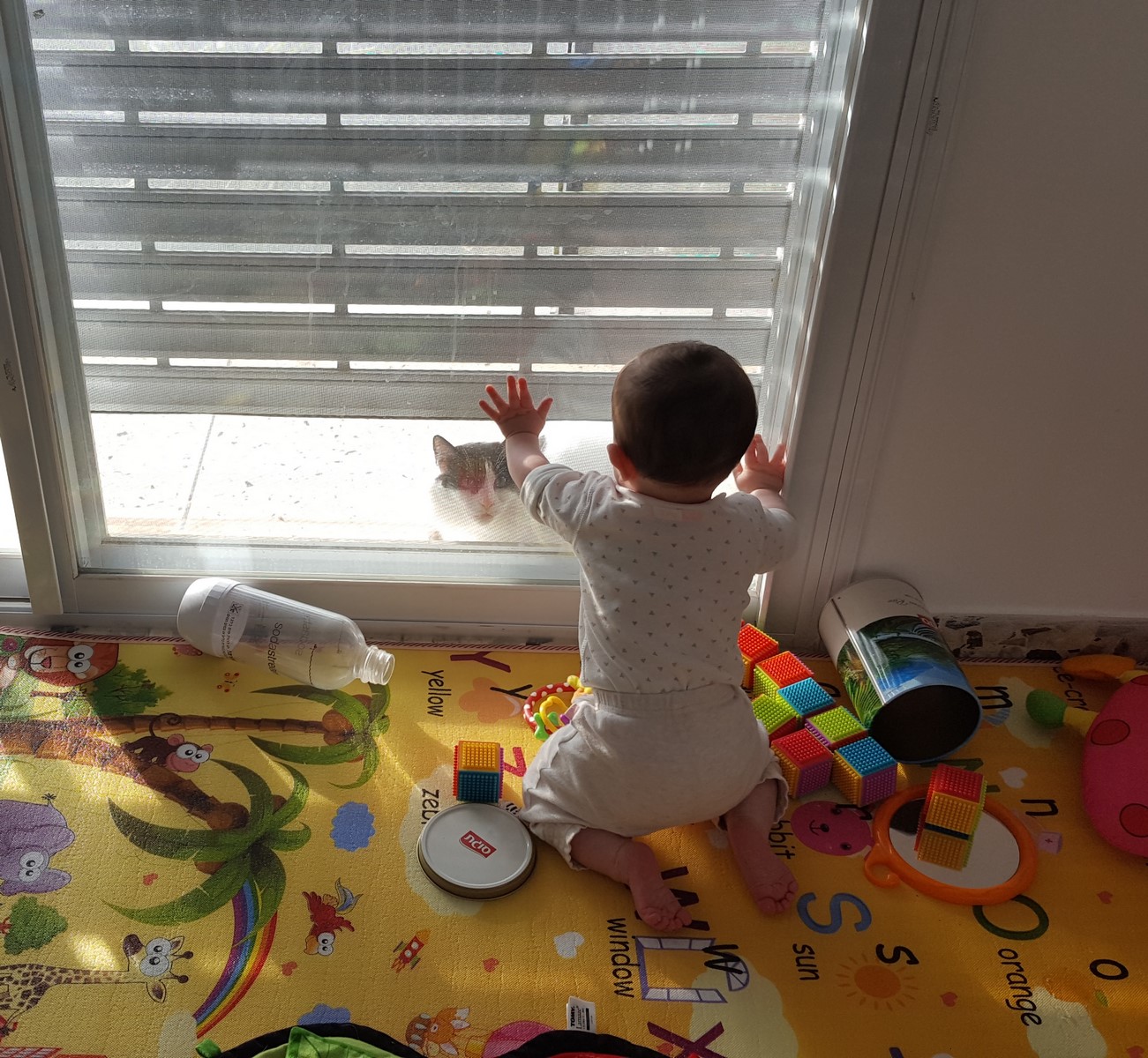
The idea came when my SO and I have decided to try improving our baby daughter sleeping habits. We tried many things, where one of the suggestions (by a professional in the field) was to get a timer-controlled night light, which will be off during the night and will be automatically turned on in the morning at a pre-defined time. Using this method the baby starts a routine, which is isolated from her parents' interference, where she learns that as long as the lights are off it is not yet the time to wake up (and yes - It actually works!).
For the last two weeks we have used this kind of mechanical timer outlet and connected a regular night light to this outlet. It worked pretty well as long as our baby tried to wake up before the adjusted time. After a while, our baby kept sleeping until the timer-controlled-light was turned on and we have noticed that when she wakes up, it is not because of the light turning on, but because of a noisy "click" sound which comes from the mechanical timer when it enables the outlet power. Furthermore, we thought it could be a nice feature if we could change the timer few minutes backward or forward if needed, but without interfering with the sleeping routine.
Well, that was the point were I could finally say "Don't worry, I'll handle it" - And took a few hours to myself to build a new timer controlled light which doesn't do this nasty "click" sound.
The solution was obvious - Lets use an addressable led strip which will be turned on and off using a controller. And if we already use a controller - Why not connecting it to the internet and control it from an app on our phone. Also, if the led strip can change colors, why not use it as a replace of the other night light (which is actually turned on all night, but as a very low red light)
The ESP8266 was a great choice, and lots of things have changed since the last time I have used it. A few years ago there was a lot of overhead when dealing with the ESP8266, I had to solder the right pins, write a code which send data to the web, get a domain and write code on a server which receive and send data to the ESP8266 and much more. After a while some cloud server started to support the ESP8266 and the ESP8266 development boards became easier to use with a USB header and standard pinout.
The Project
Cutting a long story short in case you have skipped the intro, the project consists of an addressable LED strip which is controlled by an ESP8266 using Blynk app. The strip has two options of night light and day light which can be adjusted entirely by the app, including the LEDs' intensity and amount. As a bonus, there's a DHT22 (Temperature and humidity sensor) which is also connected to the ESP8266 and sends data to the app as well.
The final app looks like that:
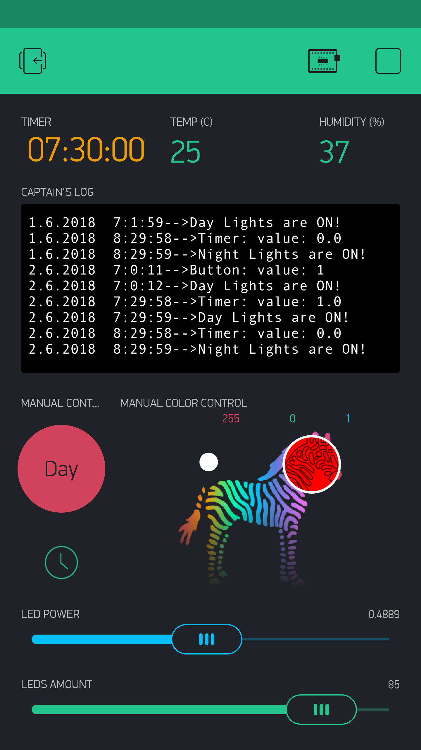
It consists (right to left, top to bottom):
- Timer to switch between night/day lights.
- Temperature and humidity displays.
- Logging terminal.
- Manual button to switch between night/day lights.
- Manual Color Selector.
- Slider to determine the LEDs intensity.
- Slider to determine the amount of LEDs in the strip.
The only important feature in the app, regarding the project's purpose, is the timer which automatically changes the LEDs color. The rest was mostly for easy debugging and the selected colors/intensity/amount were eventually written in the code as default parameters.
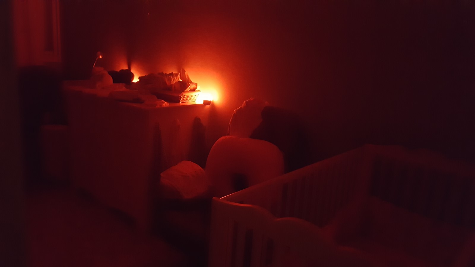
The night light looks like that (It is actually very low light, but the phone camera makes it look stronger) :
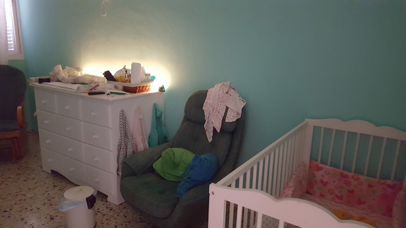
The day light looks like that:
The Build Up
The Components
The components you'll need for this project:
- ESP8266 development board
- WS2812 led strip
- Connector for WS2812
- USB cable and a phone charger - Make sure you use a quality one which can support the current you'll need for the LED strip. If you are about to use lots of LEDs, I suggest switching to a better 5V ACDC transformer
- Bonus: DHT22
If you have all these components, you can make this project pretty quickly.
The Hardware
The connections are very simple and go as follows:
(Sorry for the bad sketch - But it is just that simple! :D )
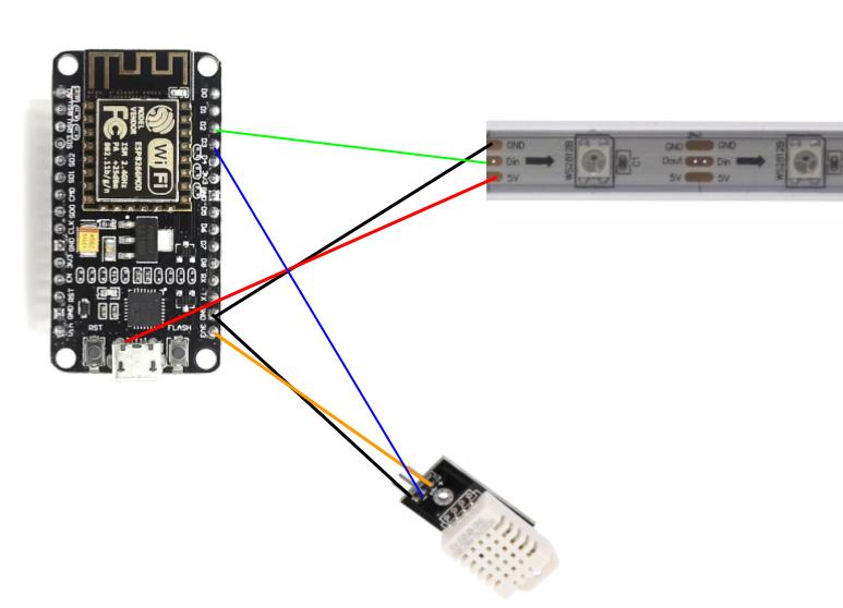
The strip has 3 connections: 5V, Line-in and Ground.
The DHT22 has 3 connections: 5/3.3V, Output and Ground.
As long as you are using standard connectors to the LED strip and an ESP8266 with a USB connector, the only wire which cannot be wired with a standard jumper cable is the 5V which is supplied to the LED strip.
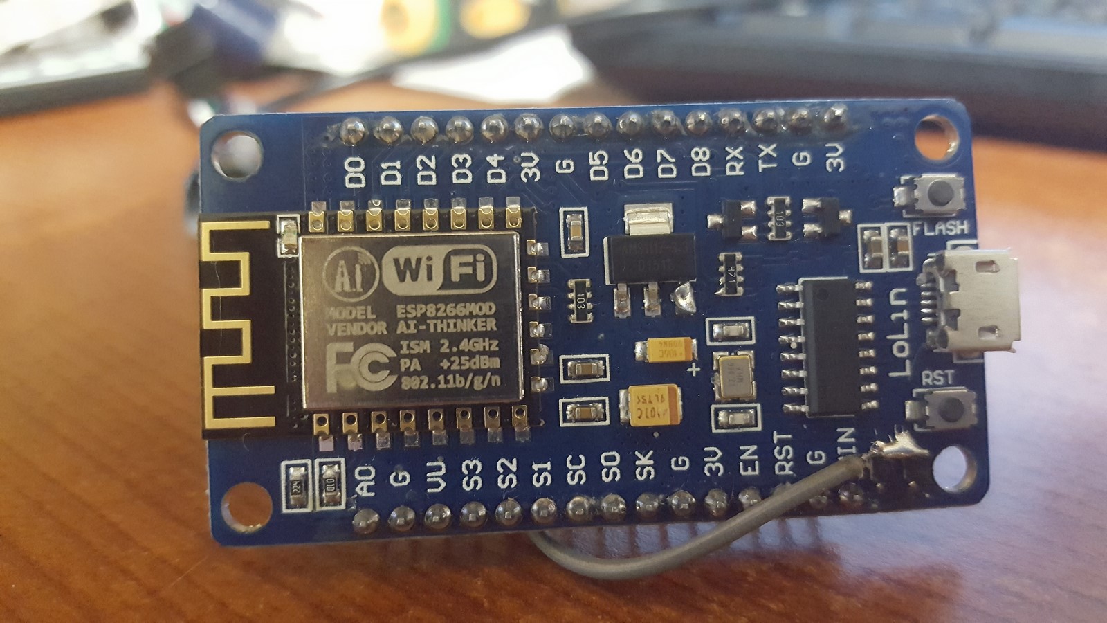
During the build-up I've done something wrong but was able to fix it, so watch, learn and don't do the same mistake. Since the USB supplies 5V, we can use it to power the LEDS. If we take a closer look at the ESP8266 development board, we see the 5V to 3.3V voltage regulator, AMS1117 which has already been seen here on the blog in several past projects.
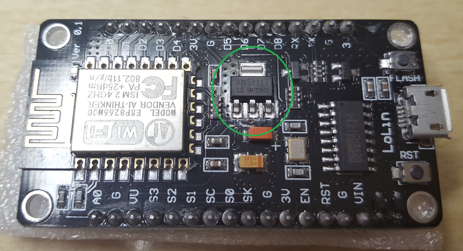
Checking its datasheet, we can see that the three pins of the regulator are 5V Input, 3.3V Output and Ground. So it seemed to me it is pretty obvious I can just solder my wire to the 5V pin and solve the power issue for the LED strip. That would be much easier than trying to solder the wire to the micro-USB connector or split the USB cable.
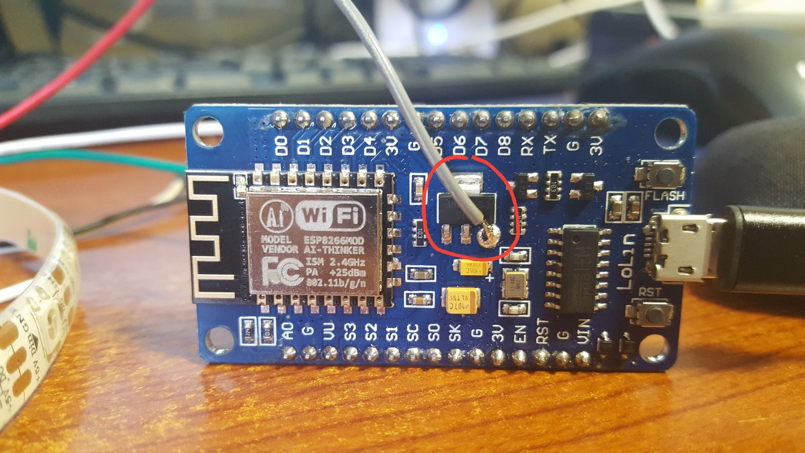
After testing the project for the first time, I wanted to see how many leds I need from the strip so I turned on around 150 of them. After a few seconds they all turned off and I smelled something burned. I immediately thought my power supply has been burnt since it wasn't suppose to handle with that much current. The power supply was OK but then I realized the ESP8266 has stopped working and thought the ESP8266 somehow was burnt (even though it wasn't really possible in this particular case). I took my multi-meter and began testing the parts on the ESP8266 module. Then I realized there's another 1KOhm resistor between the 5V USB connector and the AMS1117 pin.
Where the 5V line goes as follows:
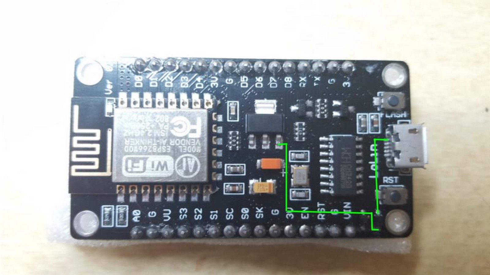
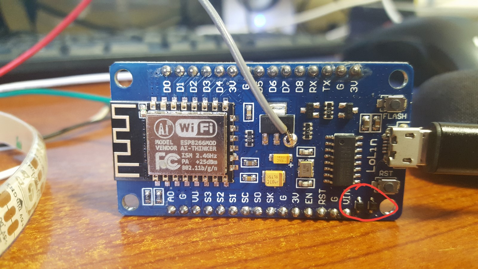
This resistor is an important part which was meant to protect the AMS1117 from high currents, so if there's a short-circuit on the ESP8266 and it draws a lot of current the resistor will be burnt instead of the AMS1117. The resistor was burnt when I tried to supply the power to the LEDS, and it shut down the entire board. Instead of switching to a new board, I short-circuit this resistor, and on the way soldered the wires to the strip at the same place.
The board was less protected now and I decided to live with that. I could have also just changed the resistor. After doing that the project was ready from the hardware point of view.
The Software
Thanks to Blynk, the software of this project is really easy to make. I uploaded my code to Github and will give some explanation here.
So how does the Blynk app works? Very Simple! First, download the Blynk app and create a user and a project, then you'll receive an authentication code which will be used in the ESP8266 code so it will "talk" with your specific project. Then, you create widgets on the Blynk app, which can be buttons, timers, displays or more advanced events. These features can send data to the ESP8266 (timers,buttons) or receive data and display it (displays, monitors, notifications). That's all! The widgets are stored on the Blynk cloud so even if your phone is turned off, they will keep sending and receiving data. Also, you can simply open the same account on a different mobile device and use the same project.
I'll start by writing about the libraries of this project, which are actually the reason why it is so simple.
#include "defines.h"
#include <ESP8266WiFi.h>
#include <BlynkSimpleEsp8266.h>
#include <Adafruit_NeoPixel.h>
#include "DHTesp.h"
#include <WidgetRTC.h>
If you are working with the Arduino IDE, simply go to: Sketch --> Include library --> Manage libraries --> and then download the "ESP8266" , "Adafruit_NeoPixel" , "DHTesp" , "Blynk" and "Time" libraries (The "Time" is used by the WidgetRTC which is part of Blynk).
defines.h- This is my library with all the definitions of my Blynk Authentication, Wifi SSID and password and more definitions.ESP8266WiFi.h- The main library to control the ESP8266BlynkSimpleEsp8266.h- Blynk library specially made for ESP8266 integration.Adafruit_NeoPixel.h- Adafruit library to control their NeoPixels, but also works with any Ws2812 LED strip.DHTesp.h- Library to get temperature and humidity data from the DHT module.WidgetRTC.h- one of Blynk libraries to receive real time clock from the internet and handle the date and the time easily.
And now going through the code main functions:
void TurnDayLights()/void TurnNightLights()- These functions control the LED strip and changing its color when day/night comes.refreshLeds()- After any event coming from the Blynk app, I call this function in order to change the LED strip colors or its other attributes.BLYNK_WRITE(VirtualPIN)- Blynk function which interrupt the code whenever a certain event happens on the Blynk app. For example: If I'll connect a button widget with VirtualPIN 1, so when the button is pressed, the functionBLYNK_WRITE(V1)will be executed. The widget I have used can be seen and explained in the beginning of this post, and the pins I've used:- V0 - Timer event.
- V1 - Button event.
- V2 - Changing LEDs power/intensity event.
- V3 - Changing LEDs amount event.
- V5 - Changing LEDs Color manually event.
void sendSensor()- This function reads the data from the DHT22 module and sends it to the Blynk app, also through virtual pins.BLYNK_CONNECTED()- Lines of code which will be executed when the ESP8266 has managed to connect with the Blynk app.void setup()- The init process.void loop()- Basically this is the "main" code, but all it does is making sure Blynk runs, and every X seconds reads data from the DHT22
In some of these functions, I've used the terminal widget which is connected to V4. With this widget I can simply debug everything I want. When debugging, instead of using Serial.println() and connect to ESP8266 to my computer, I can simply write it to the widget terminal and receive all I need to know.
Notice that in order to build this project, all I have needed was only the timer widget, but the other widgets were added as well so it was very easy to fine-tune the right setup for my baby daughter's room. After finishing the hardware and software, I could already install it in the room, close all the windows, and play with the LEDs amount,intensity and color until I was happy with the results, all using the Blynk app. Then I could define the results as defaults in the code and start using the product.
A Few More Words About Power Supplies
The LED strip can take a lot of amperage, and the right power supply should be selected, otherwise it will not turn on the LEDs or worse, get burnt and fill the room with smoke.
For instance, 100 WS2812 LEDs on full intensity, white color, can take up to 6 amps! A high quality phone charger can supply around 2 amps, and low quality can get to 1 amps. I've written about that a bit on another post.
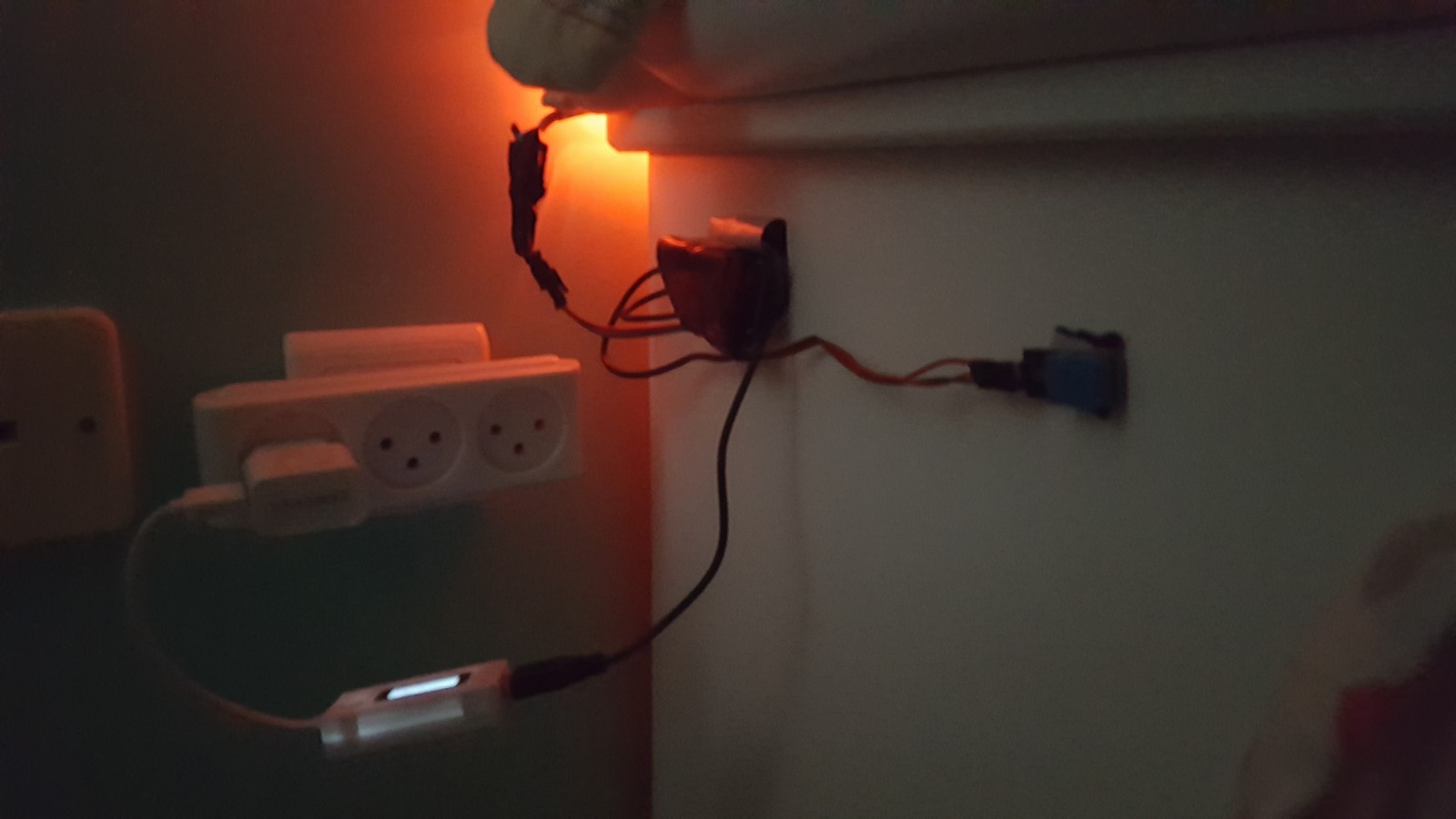
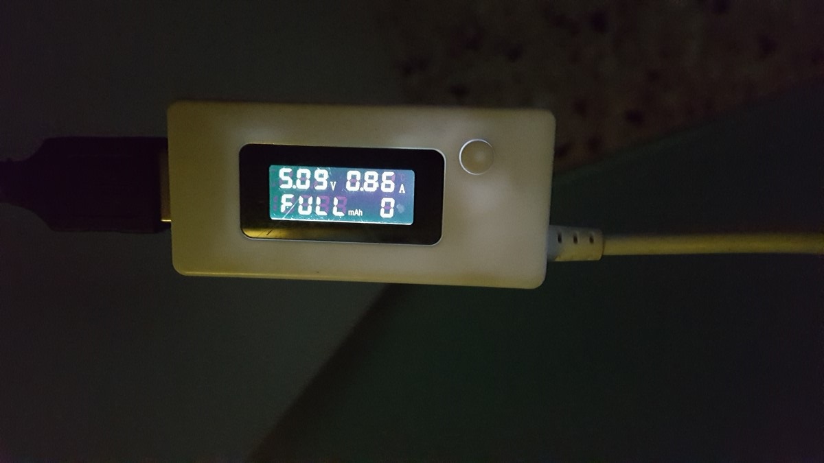
The setup I've chosen (84 LEDs, 0.5 intensity, red/yellow colors) takes a bit less than 1A, so a good phone charger was enough. While setting up the hardware, I've used a very useful device - It consists of a small display which let you know the amount of voltage and amperage you are using. In the next photo you can see my setup, the device is connected between the phone charger and the ESP8266:
Then, using the Blynk widgets I've mentioned before I could test the amount of amperage in night/day scenarios. My selected scenarios looks like that on the display:
Night scenario, 84 LEDs, 0.5 intensity, red light - 255, green light - 15:
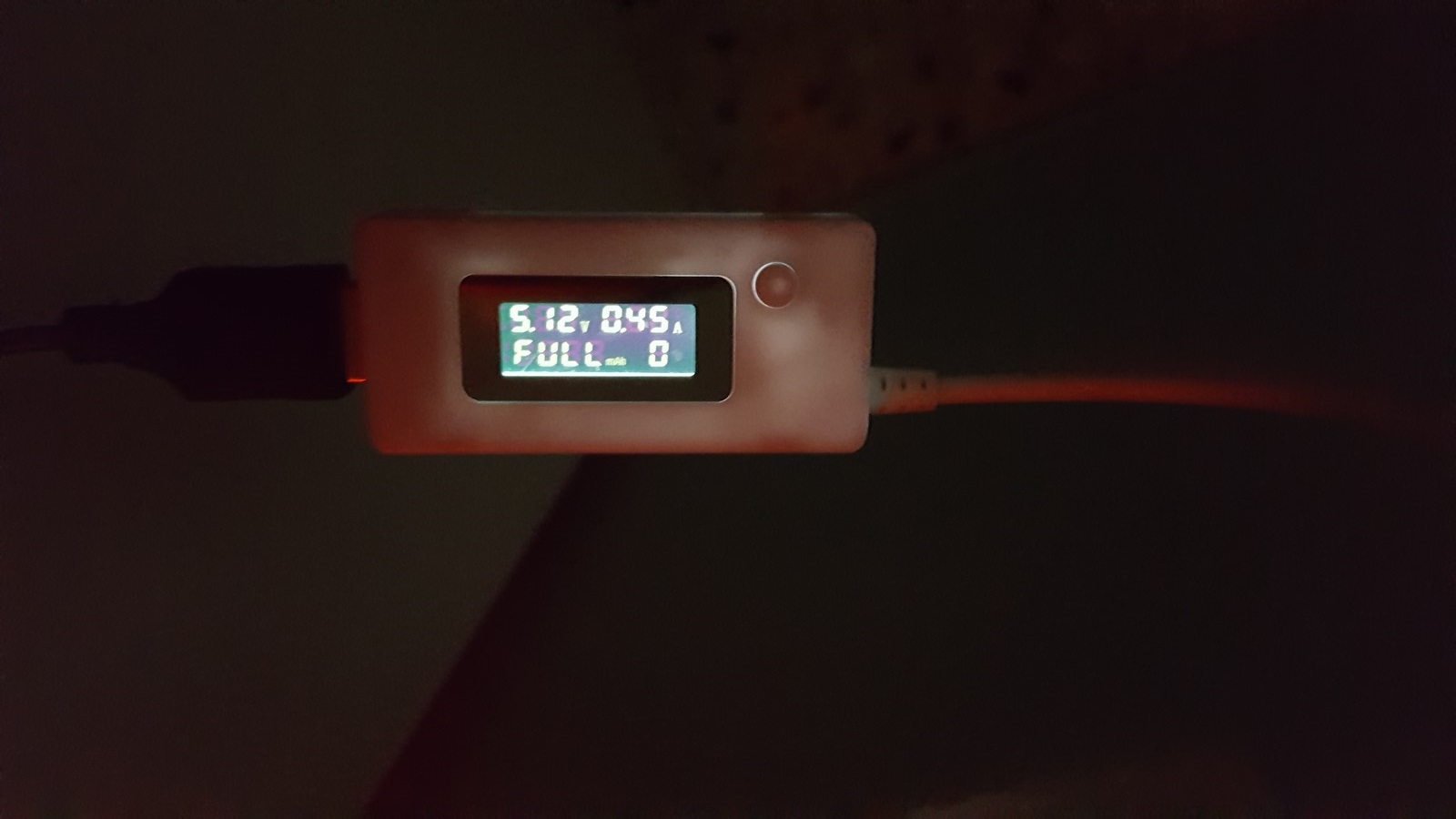
Day scenario, 84 LEDs, 0.5 intensity, red light - 255, green light - 128:
As a final thought, if you actually going to use my code to build a night light for yourself or for your kids - I advise not to use the blue color in your final setup since it can delay your sleep and keep you awake. There are many studies on that subject, here's a quote from an article I found:
The consensus is that the blue light that LED screens give off can slow or halt the production of melatonin, the hormone that signals our brain that it's time for bed.
Hope you have enjoyed the post and the project, if there are any thought, comments or questions you are welcome to write to me in the comment section down below. I'll be back soon to write about more things I have made in the last few months.
AA