Here in Israel the climate can get quiet extreme, about 45° (113f) and about 90% humidity.
For a laptop, it gets even hotter, when its internal parts can achieve even 90°C!. The hotter it is outside, the harder for the laptop to cool itself. And, the stronger the laptop, the hottest it get, So it is crucial to have a laptop cooler.
I have a COOLMASTER laptop cooler:
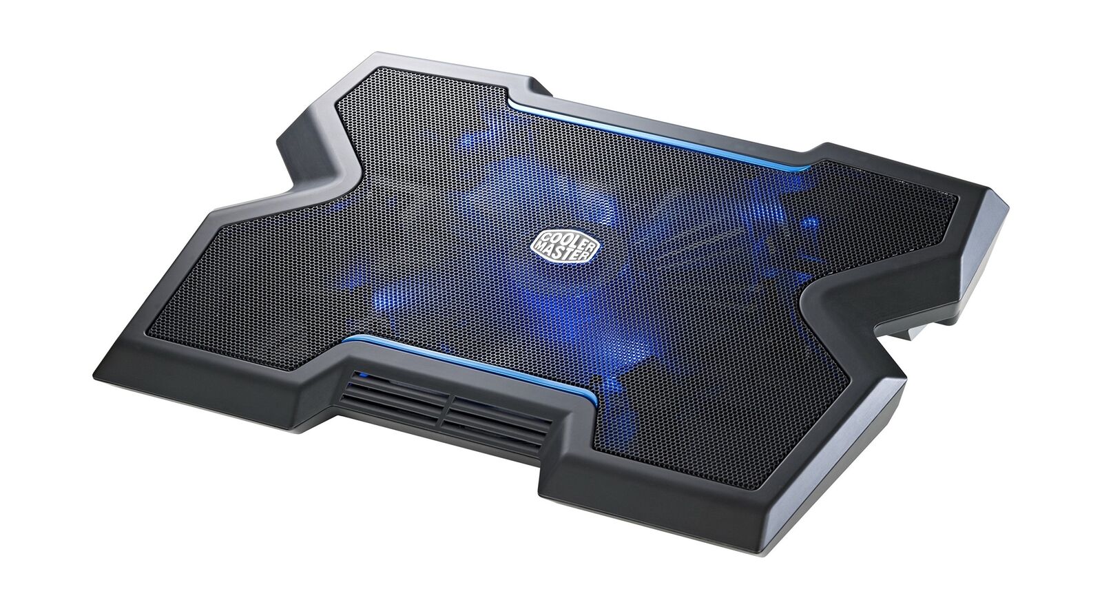 It's quite good, I have it for almost 6 years.
The project:
As you can see the cooler have blue leds builtin.
Well today I'm going to replace these leds with ones that change their color accordingly to the laptop exhaust temperature.
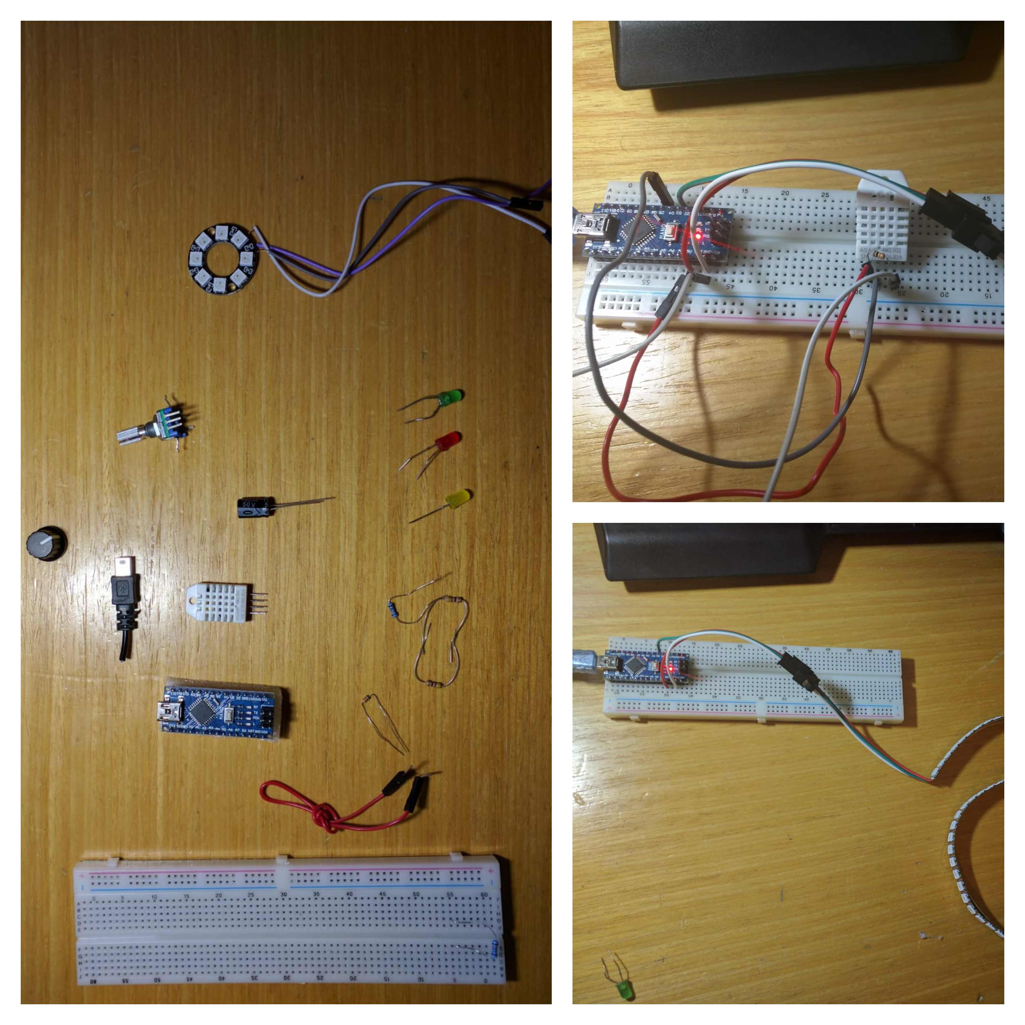
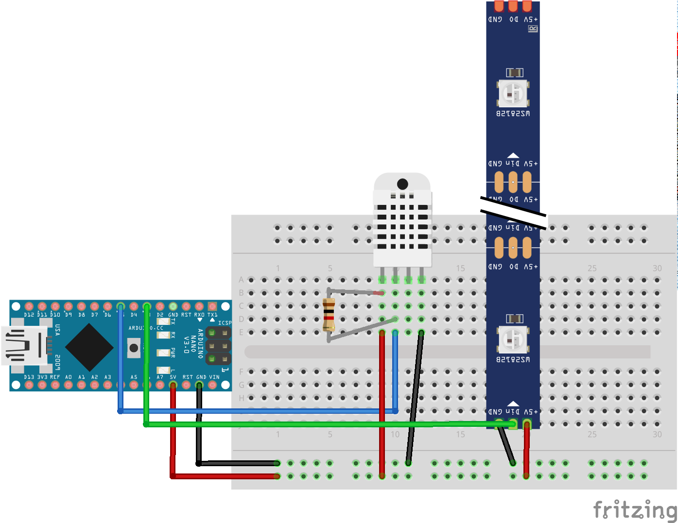
Things I used for this project:
- FastLed library, for controlling the NEOPIXLES.
- DHT library, for sampling the temprature of the laptop exaust.
- Also, installed the Adafruit_Sensor library, it appears that the DHT lib requires that.
- 1k resistor, for DHT22 voltage devidor.
- Some jumper wires.
- Arduino nano
In this post Im trying a new methodology:
The SPRINT
.It took my 5 minutes to jig up my Arduino nano with FastLed library and an example from this tutorial, and run beautiful led display :)
5 minutes later:
I've added sampling temperature and humidity so now the Arduino samples temp and has a pretty led show display.
The DHT22 sensor library is quite straight forward. Moreover, I already had some experience with DHT22 sensing (in the babysleeper project).
So It seems that everything is set-up, Now its time to write some CODE!.
If you want to skip all the FUN, the code is on Github.
Well, by now i have a light show, and temperature sampling.
What I wanted was to connect the two, and interpolate from current temperature the desired color.
In the babysleeper project I changed the color by changing the RGB values, It was convenient then, because I received an HEX representation of the RGB values, from there interpolating the R G B is straight forward:
If the value recieved is #ffcc99, Than:
- R = 0xff
- G = 0xcc
- B = 0x99
Each color was represented as 1 Byte (hence possible values are 0-255).
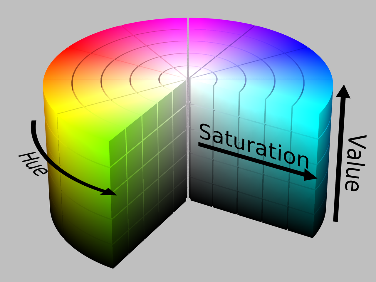
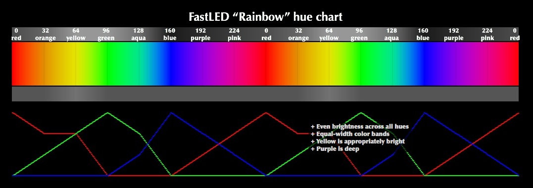
In this case, I wanted to change color based on a single value (the temperature), The easiest way to do so, is modifying the HSV values. Wait, what is HSV?
From this great explanation, I've learned that:
Working with raw RGB values in your code can be awkward in some cases. For example, it is difficult to work express different tints and shades of a single color using just RGB values, and it can be particular daunting to describe a 'color wash' in RGB that cycles around a rainbow of hues while keeping a constant brightness.
To simplify working with color in these ways, the library provides access to an alternate color model based on three different axes: Hue, Saturation, and Value (or 'Brightness'). For a complete discussion of HSV color, see HSL_and_HSV , but briefly:
- Hue is the 'angle' around a color wheel.
- Saturation is how 'rich' (versus pale) the color is.
- Value is how 'bright' (versus dim) the color is.
Within 25 minutes, Iv'e managed to learn how to use the HSV wheel to my favor:
Setting HSV Colors:
So now, that i have a temperature samples from the DHT, and learned how to work with HSV values, I can interpolate between these two, Using the MAP function:
 At first I wrote:
int mapped = map(temp,26,HIGHEST_TEMP_REACHED,160,360);
The desired range is 160-360.
Because the way the HSV wheel is described, I wanted to travel between blue to red (or 160° around the color wheel to 360 °).
BUT, Accordingly to FastLed, to make your code smaller, faster, and more efficient, the FastLED library uses simple one-byte values (from 0-255) for hue, and for saturation, and for value.
So now it looks like this:
int mapped = map(int(temp),MIN_TEMP,HIGHEST_TEMP_REACHED,160,255);
Where:
- MIN_TEMP - always updated
- HIGHEST_TEMP_REACHED - always updated
- 160 - the blue HSV value angle around the wheel.
- 255- the red HSV value angle around the wheel.
The HIGHEST_TEMP_REACHED and MIN_TEMP are values I want to store between Arduino restarts.
Using EEPROM:
Well, I already know how to work with the NVS (learned that in the babysleeper project), now I want to learn how to use EEPROM:
EEPROM macro stores a BYTE in a curtain adders, for me, a Byte is perfect. Because the maximum value of a byte is 255, and i hope it wont get that hot where i live. So there's no problem storing the temperature, using this simple call.
Now that i know how to store data between restarts, I want to maintain highest temperature reached:
if (round( temp) > HIGHEST_TEMP_REACHED){
    HIGHEST_TEMP_REACHED = temp;
    EEPROM.write(addr, HIGHEST_TEMP_REACHED);
}
Using this If condition I make sure that the highest temp reached is always updates, it is crucial for the MAP function.
NOTE: I'm also saving in the EEPROM LOWEST temp reached - Since winter is coming, I want map to map accurately all seasons.
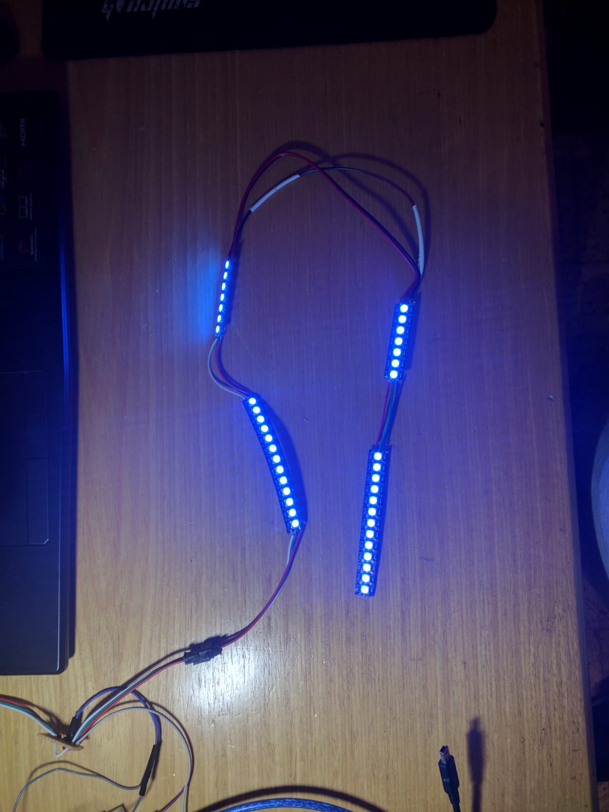
Now that the code is ready, its time to spread my wings and leave the BREADBOARD. After another 20 minutes of soldering, I have a proper rig:
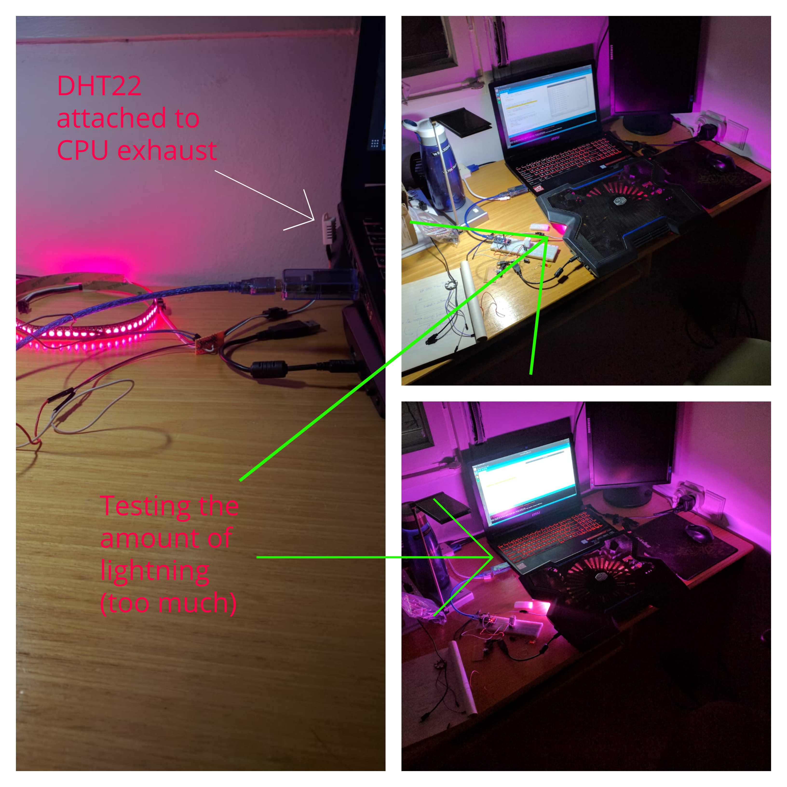 NOTE: It seemed that I was using too much leds (70), hence too much light. I needed to cut the LED strip.
Now I want to know:
- What is the hottest temperature the exhaust of my laptop can reach?
- From which exhaust? ( the CPU exhaust? the GPU exhaust?)
So, lets do some research:
As for core temperatures:
The nominal temperature range for the CPU and GPU are similar: 35-45°C when their workload is light, 85-95°C when their workload is heavy.
Thanks to Own Or Disown reviews:
He reviewed the same laptop I have, back when it was new, actually - He helped me decide whether to buy it or not, as his slogan says - "Tech decisions made easy" :).
In his review, he shows a thermal image of the exhausts of the laptop, while its in full load.
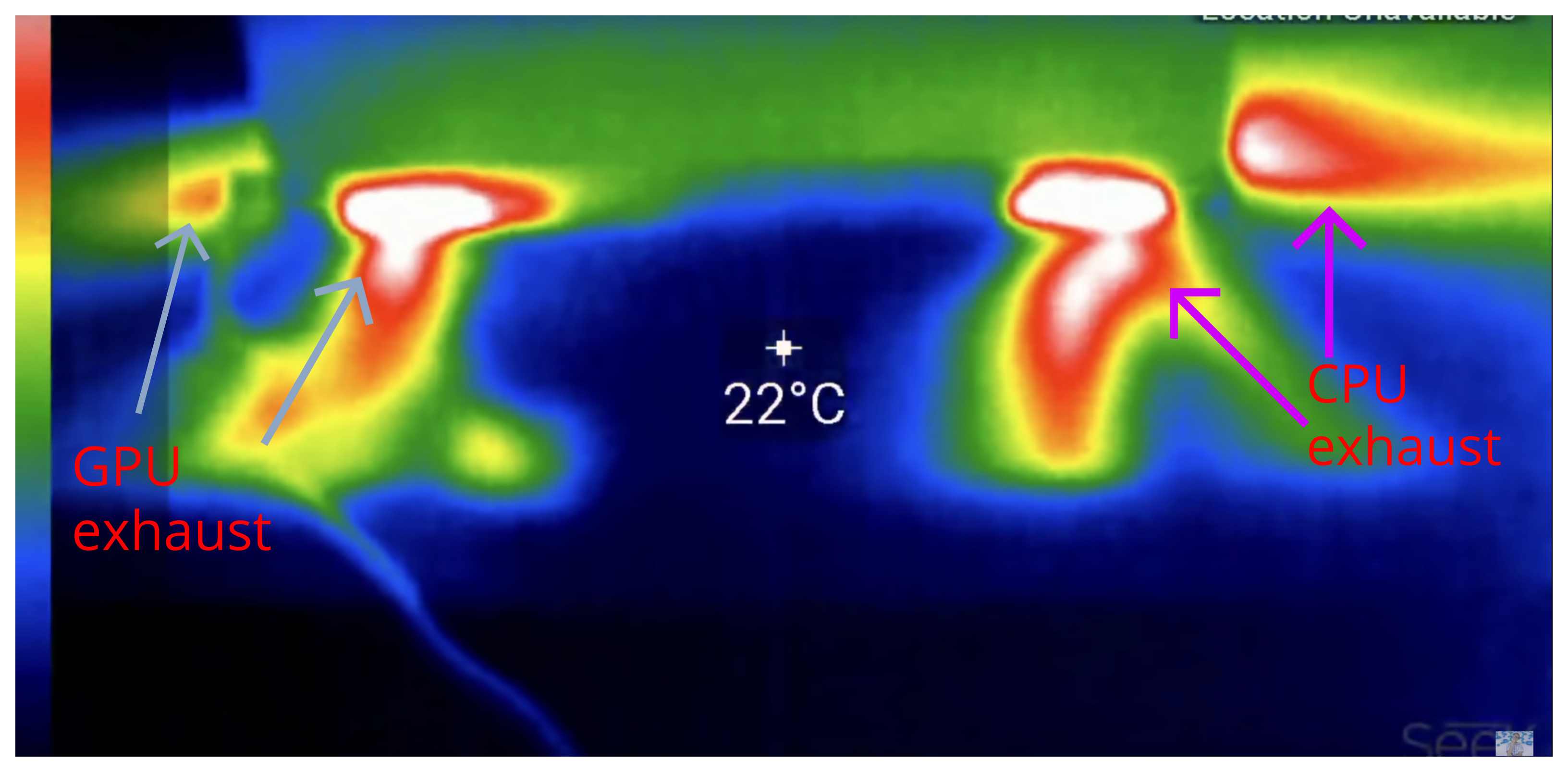
It seems that the CPU exhaust is hotter that the GPU.
In order to figure things out, I hot to trot to test my laptop exhaust temperatures. And there's no better way to test this, than a session of Assassin's creed odyssey (ultra settings, 40-50fps).

NOTE: before starting this test, highest temp which was stored in EEPROM was 32°C
After one hour of playing, highest exhaust temp reached was: 44°C, keep in mind that this is the exhaust temp, not the core itself.
While letting the laptop cool itself, I saw that the led never reached to blue color. It seems the minimum_temp value in the ino sketch is too low. If the computer nominal temp range between 34-45, then I should adjust the minimum_temp variable, so that leds will light in blue, in these temperatures.
After adjusting the minimum_temp, the colors clearly changing back to blue.
So, IT WORKS!
Now all I have left is to put it all inside the COOLMASTER laptop cooler.
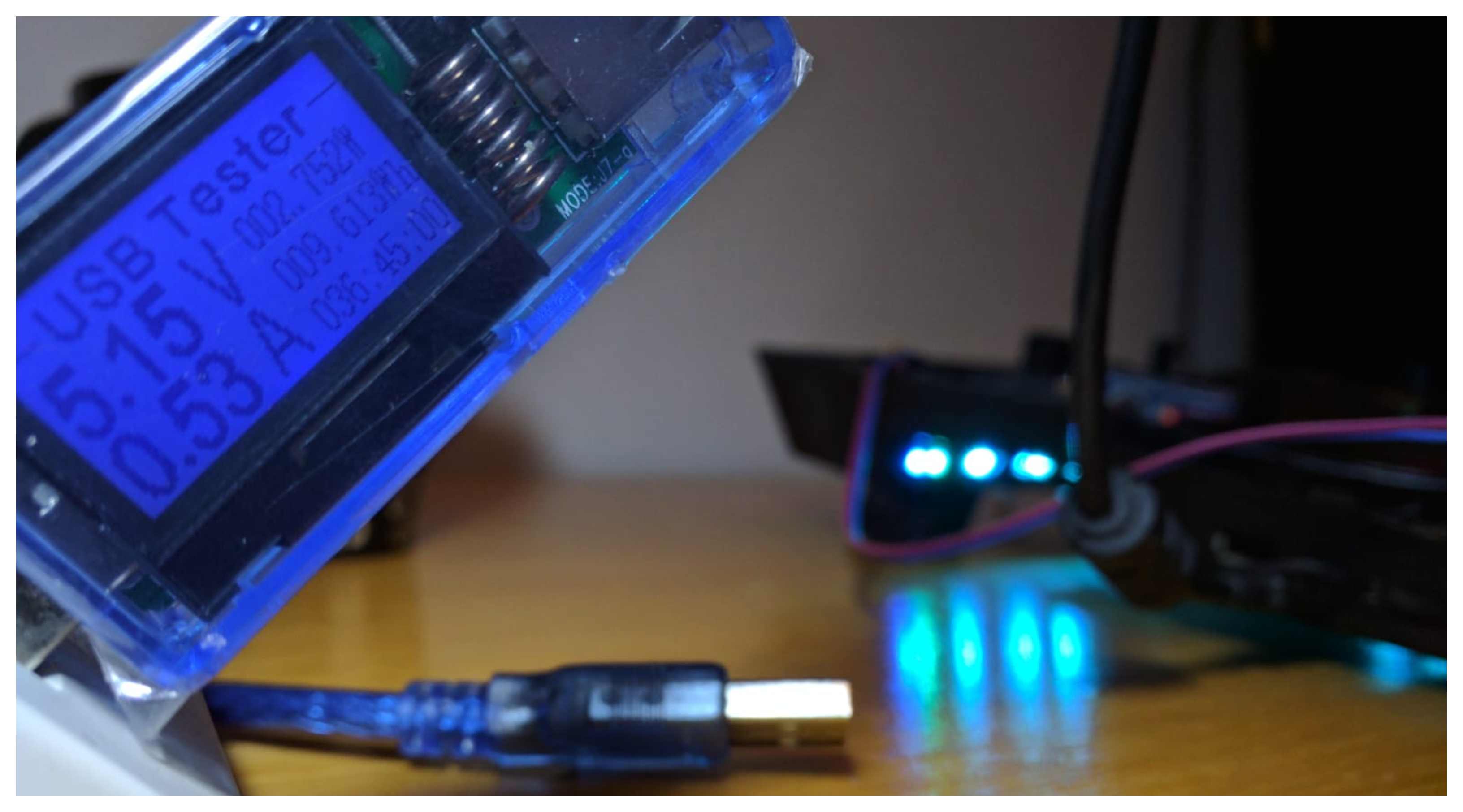
Before that, lets talk about power usage:
- The cool master requires about 0.5a to work with fan on full power and (built in) leds turned on.
- The kit i made requires another 0.4a to power app all the leds (70 leds), when the V of HSV (aka value) is on highest.
Well, now after I have reduced the leds number to 40, and disconnected built in leds (iv'e connected the arduino NANO instead), the power consumption of the COOLMASTER (fan on full, arduino connected, and NEOPIXLES are on) is STILL AT 0.5a!, which is amazing, because i was afraid that overall power consumption will reach over 1 amp, and that is not good..
Until now, the overall time spent on this project: 1 hour
- 25 m - writing code and bring up a prototype.
- 20 m - writing the post itself.
- 15 m - shortening the LEDs strip, and re-shouldering it so it could fit inside the COOLMASTER:
 The leds CUTTING area was small, thus after cutting it was hard to perform a good and strong soldering there. It took me a few times until the leds hold up together all the curves inside the COOLMASTER.
Well, to be honest, wiring the COOLMASTER took the most.
This was the project's final stage, everything had to work perfectly before starting to hot-glue everything together.
Within 90 minutes, I finished fixing everything inside the COOLMASTER, and I was done!.
Everything hooked up inside the COOLMASTER:
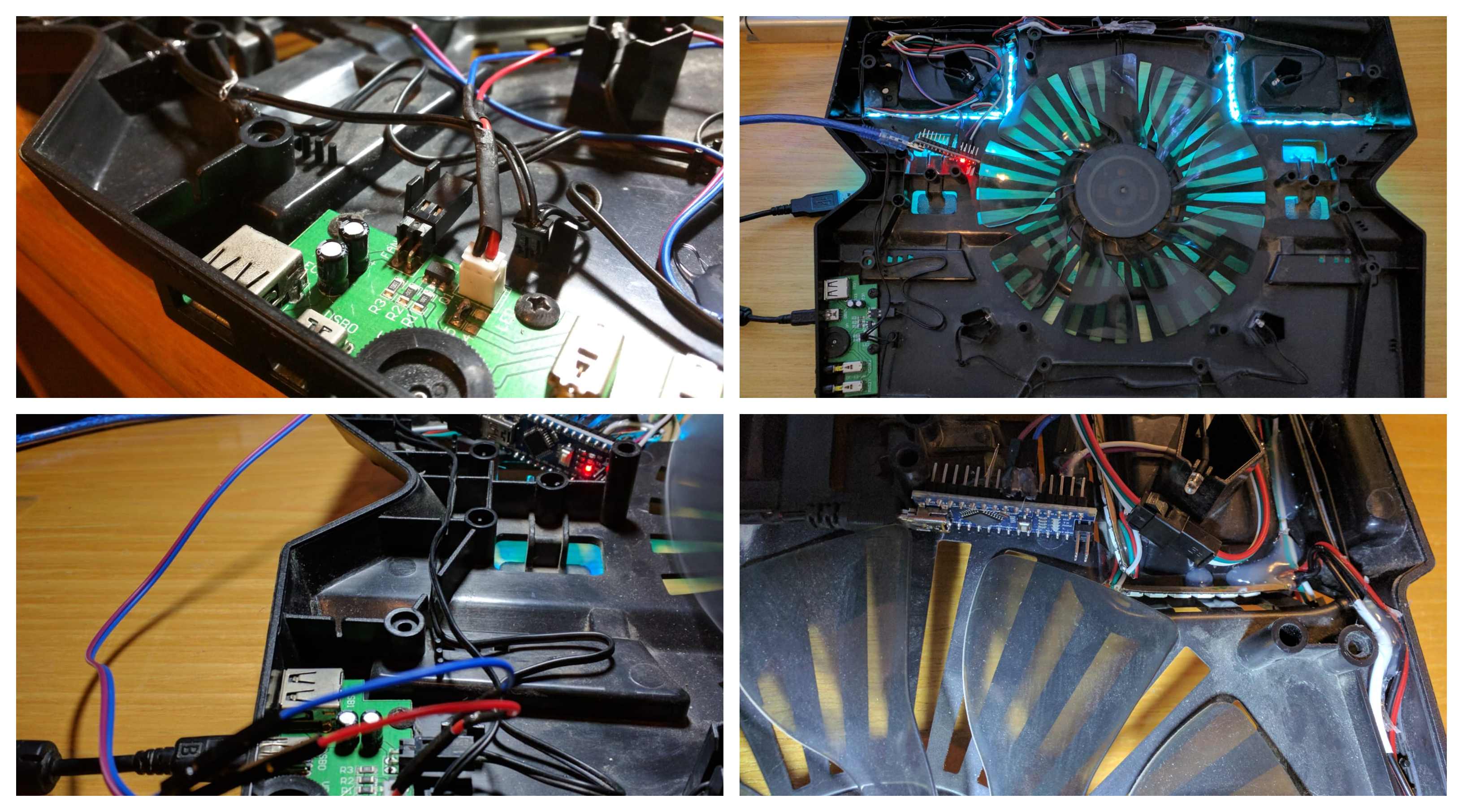
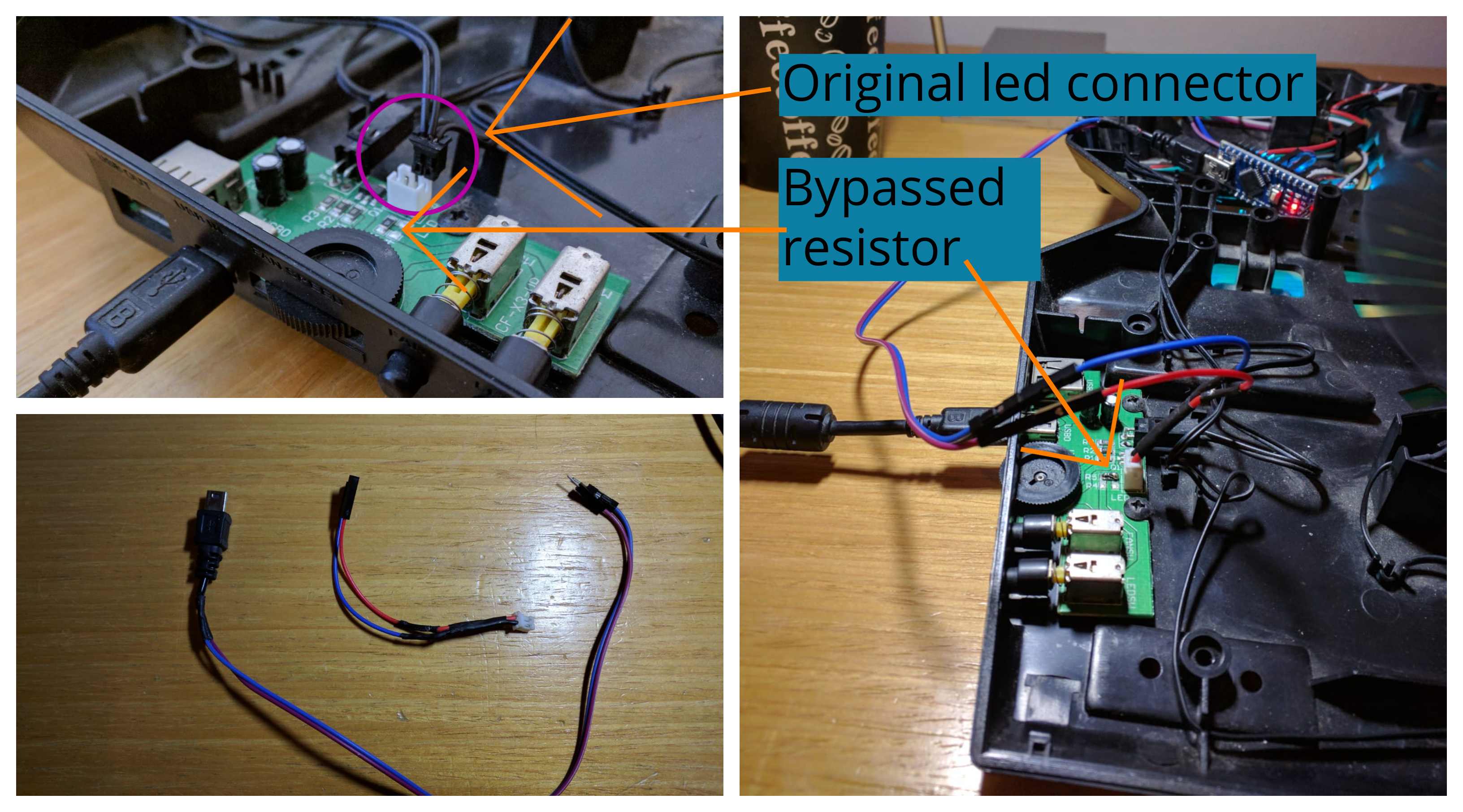
I've connected the arduino instead of the builtin-leds:
When working with the original LEDs connector, I saw that the arduino is not getting enough juice.
Well apparently the built-in led has a 100Ω resistor, which limited the current only to 50ma:
To figure this out i used simple ohm law: V=RI:
Where V=5 volts, and R=100Ω, thus I=0.05a.
And we saw earlier that the Arduino itself (powering 70 leds) took nearly 0.4a. which is 8 times more than the current supplied by this resistor.
Hence I bypassed it:
So..... (drums)..... I give you the final product of my project:
This is SPRINT signing off.
It took me 150 minutes to complete this project from zero to hero.
Sprinting is a nice approach, quite exhausting, but keep you on tracks until the end. I don't know if i'll adopt this approach, but it is nice to experience it - and know that mini project can be done within couple of hours.
Cheers,
Gal Brandwine.