
Recently, I got a new board at work, with a new sensor (STM's latest).
I've been tasked to write a driver for it to expose its needed capabilities to our application running on Zephyr.
A decent task, not too shabby.
When bringing up a board, one must first ensure that all pins and lines are connected according to the data sheet. One way to do it is with a small program that toggles all the CPU pins, and a fluke - measuring the expected pin gets turned on (in my case: changed from ~0 to 1.8v ).
Next, implement a minimal program that reads the HWO_AM_I register of the sensor.
This register contains the sensor ID, ensuring we are communicating with the expected sensor. The ISM330BX is embedded in the new board with a SPI communication layout. So, this minimal program we'll need to support SPI communications.
The dataset provides the HWO_AM_I address; reading it is straightforward.
If I succeed, it means I have correctly configured the SPI, i.e: * Bit order is as expected (LSB/MSB) * Communication frequency is acceptable * The MISO/MOSI wires are connected correctly.
This also confirms that I'm communicating with the correct sensor, and we can proceed with writing the driver. yey!
But if things are not working, here's why I used an Oscilloscope :(
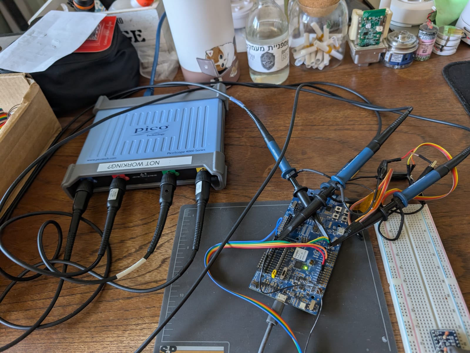 [Wires are a mess; suggestions for better organizing the wires are welcome.]
I already know things are configured as expected:
- I've checked the wires - V.
- I've checked the register address - V.
Yet when reading the HWO_AM_I register over SPI, I get either 0x00. Connecting an Oscilloscope will help "sniff" the SPI wires and understand the bits that flow over the MISO and MOSI wires.
I use PicoScope 4000 Series (borrowed it from work, they cost too much to have one of my own).
Getting 0x00
0x00 means there's no feedback from the sensor:
- Either it doesn't get any power.
- Or is there an issue with the probe wires?
- Or (if using Zephyr RTOS like me) the DTS (A devicetree is a hierarchical data structure primarily used to describe hardware) is not configured correctly.
Investigating:
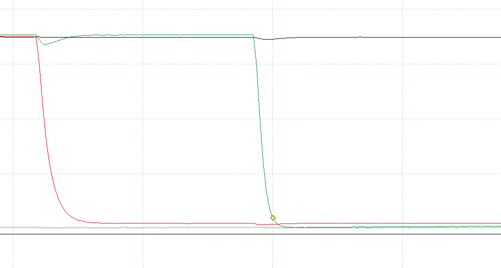
I've set up trigger events on the PicoScope to watch the ChipSelect (CS).
Usually, when communicating over SPI, when CS falls to ~0 it means 'start SPI communication'.
In the image below, the CS line (black) didn't fall to ~0 as the others did:
Knowing the wires are connected correctly on the hardware side, I overlooked the firmware side - finding out the DTS wasn't configured correctly:
&spi0 {
    status = "okay";
    compatible = "nordic,nrf-spim";
    cs-gpios = <&gpio0 07 GPIO_ACTIVE_LOW>; <-------- Actually, the CS is connected to gpio1 07
    pinctrl-0 = <&spi0_default>;
    bme280@0 {
        compatible = "bosch,bme280";
        reg = <0>;
        spi-max-frequency = <1000000>; /* conservatively set to 1MHz */
    };
};
Another iteration - fixing the DTS, building, flashing, and voila!
You can see the CS line (black) falls to ~0 along other lines:
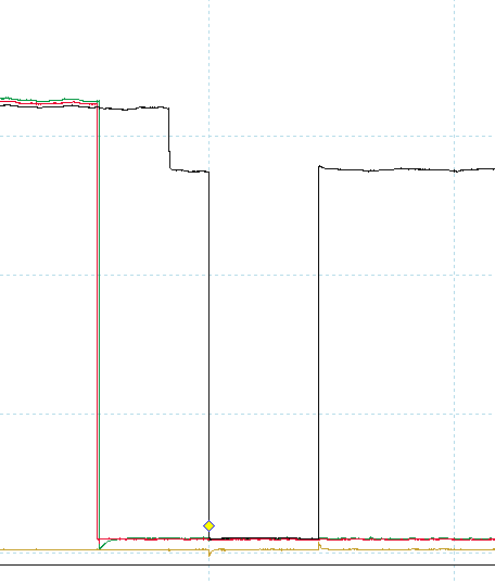
Yet, the result of the WHO_AM_I is still 0x00 (also in the image above - the communication is not presented as SPI's digital waves, but rather messi). It means the MISO and MOSI wires are not behaving as expected!
From the DTS snippet above, the MOSI/MISO and clock are defined here - pinctrl-0 = <&spi0_default>;.
Looking at the spi0_default definition:
    spi0_default: spi0_default {
        group1 {
            psels = <NRF_PSEL(SPIM_SCK, 0, 27)>, <--- Actually I need <0 31>
                <NRF_PSEL(SPIM_MOSI, 0, 26)>, <--- Actually I need <0 30>
                <NRF_PSEL(SPIM_MISO, 0, 29)>; <--- Actually I need <1 08>
        };
    };
Another iteration - fixing the DTS, building, flashing, and voila (hopefully)!
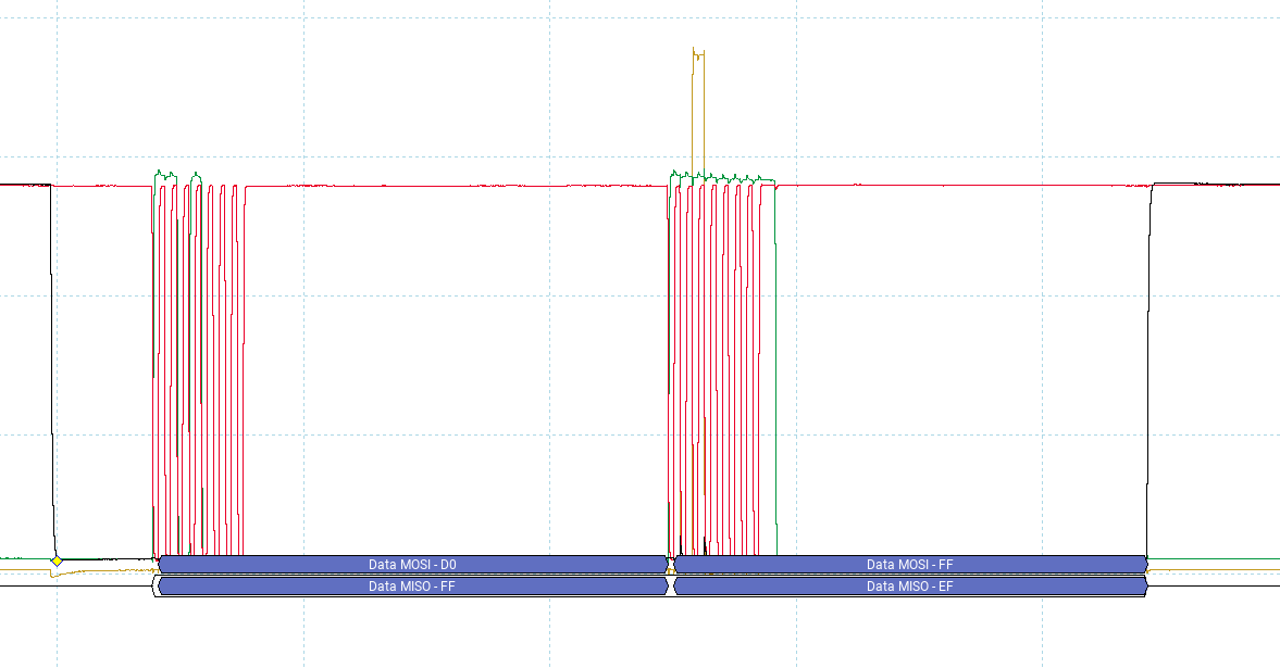
In the image below, we can see the SPI communication!
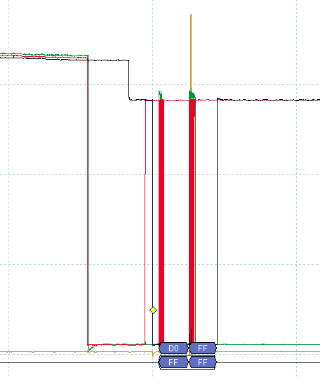
Zooming in, looking at this image from left to right:
- MOSI (master-out-slave-in) command "read register WHO_AM_I register (from the data sheet address 0xD0)
- MISI (Master-in-slave-out) response from the MISO line: value 0xEF - not the expected response value :(
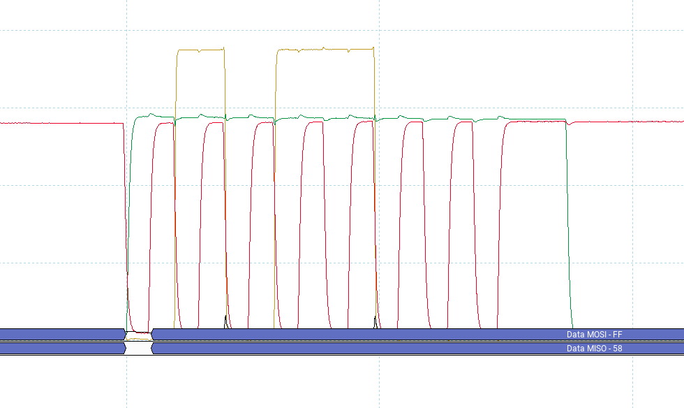
Replacing the MISO wire on my setup did the trick! Now it is visible - MISO responds with the expected value 0x58:
The red line is the clock, so we can see where there are 8 ticks (which means 8 bits, 1 byte)
The yellow line is the MISO wire; when it is low, it is 0, and 1 when high.
So, from left to right, we get:
01011000b = 58h
The expected response when reading the WHO_AM_I register yey!
We are communicating over SPI with our new sensor, Hazzah!
Now the real project can begin!
Thoughts
Using an Oscilloscope is something super helpful; it helps debug digital communication.
And makes board-bring-up shorter
Cheers Gal.