Last week I once again participated in the great Geekcon event. If you haven't heard of it, Geekcon is an one weekend event where people come to created massive useless projects. The main idea is to enjoy the process of building the project rather than completing it. You can also check other Geekcon projects I wrote about in the past: Scorbot Learns to Draw and The Pet Authorization Project.
During that event I re-used an obsolete project from two years ago, while doing so it reminded me I have never written about the original project on the blog. So I decided to document both the original project and its re-use - There are a lot of cool slo-mo videos so check it out!
The first Project is the Real-VR-Shooter. In this project we built our own automated Nerf gun, using three motors, two for rotation left-right and up-down ("yaw" and "pitch"), and one motor for reloading a bullet/dart. The "shooting" was done using air pressure. The gun has two cameras on its front part, and their stream goes directly into a VR kit (Oculus Rift) as a stereo system. The person that wears the kit, see the world from the shooter point-of-view and when tilting the head the shooter moves with him. Finally, object detection algorithms are running on the video stream showing the player who to shoot and who is innocent. Here is how it looks like during the building stage (Unfortunately I don't have any movies from the final use). Rotating:
And shooting:
In the second project (After two years), we re-purposed the shooter as a computer program which can track objects and then shoot them. Then we built a target range where the shooter has the hit, while other people can use manual Nerf guns and try to hit the target range as well.
The code repositories for both projects are on my Github page:
- Project 1 - The Arduino code is on this folder
- Project 2
All the 3D printed parts of the shooter can be found here on Onshape.
The Real VR Shooter
General Discription
This project has several components, but in general composed by three items:
- VR kit (Oculus Rift)
- Computer
- Shooter
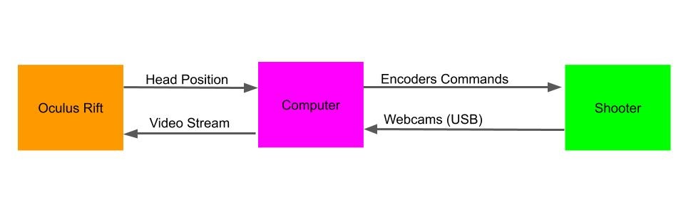
Here is the shooter pipeline, followed by the components description:
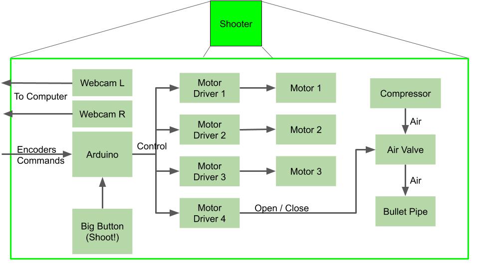
- Shooting Button - Connected to the arduino as an interrupt.
- Four Motor Drivers - We used two L298 module which has two drivers on each. Three drivers were used to control the motors and one to open the air valve.
- Three "strong" DC motors (I'm explaining later-on why we choose DC motors).
- Air Valve
- Air compressor or a bicycle pump and an empty coke bottle (Tried both and both work).
- 3D printed structure to fix all the components and of course Nerf darts!
- Two webcams, mounted to the shooter and connected to the computer USB ports.
- Arduino Mega - Must be "Mega" since we need four interrupts pins and many more IO pins. The arduino performs the next pipeline:
- Listens to the UART stream to determine if a new position command has been sent.
- Keeps the last position command and activate the motors accordingly using a PID algorithm.
- Receives interrupts from the motors' encoders and maintains counters to know the current position
- Interrupt by the shooting button and open the air valve for 100 milliseconds, then activate the third motor to load the next dart.
The computer program pipeline:
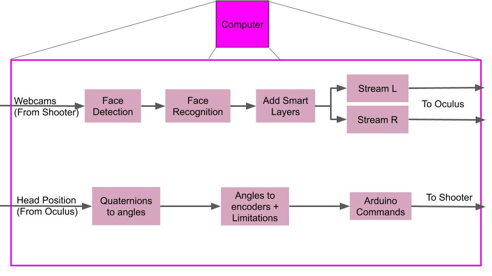
- Receives the webcams video from the shooter
- Finds all the faces in the current image.
- Recognizes the faces using pre-trained computer vision algorithm, and paints a green or red bounding box around the faces if they are "wanted" or "innocent".
- Creates a stream with the new images and stream it to the left and write screens in the VR kit.
- Receives head orientation from the VR kit.
- The orientation is received as quaternions and the program transforms it to Euler angles.
- From Euler angles only the pitch and yaw are used (roll was not implemented). The angles then transformed to encoder values using pre-calculated weights.
- Finally, the encoder values are sent to the Arduino, and back to listen to the new orientation.
Some Tips During Build Up
Motors
About two and a half years ago, we first met to work on this project at Aviv's place hatahbiviya (If you live near I encourage you to come over and check it out!). We aimed it to work with our robotic arm from previous posts (Scorbot), that will hold a Nerf gun and shoot at people. It took us very short time to make it work, but there was one problem, the arm was super slow and didn't react fast enough to the head movements:
So we decided to build our own system. We started with two step motors connected with some scotch tape and play-dough and the results seemed pretty good at first glance:
It seems good for an autonomous shooting machine, but when wearing the VR kit it didn't feel so good since the stepper motor movements are not smooth and the video stream didn't feel natural enough.
Servo motors which are strong enough to carry so much weight were pretty expensive so we decided to go with DC motors and encoders. I wrote here a lot of information about DC motors with encoders if you wish to read.
PID Control
In order to control DC motors we must use some more sophisticated control than just ON/OFF. This encouraged me to learn and implement a PID controller. How it works? Check the next image from Wikipedia:

In our case:
- The input $r(t)$ is the position (or encoder value) we want our motor to reach to.
- $y(t)$ is the motor's current position (or encoder value).
- $e(t)$, as seen in the diagram, is the delta position we need to fix.
- $u(t)$ is the action we need to give to the motor so it'll change its position such that $e(t)$ will diminish.
So the action $u(t)$ is a sum of three equations, and here I'll try to explain the intuition behind each one (at least my intuition).
- P - Take the error, multiply it by a constant, and that's it. Here the intuition is pretty straight forward. If the error is positive or negative, move to the right direction to close this error. If the error is small or big, determine the motor's power by these values and make small or big movements. Using this equation only can be problematic for two reasons when we plan a robust system. First, in case of very large errors the motor might fix the error too aggressively and pass over the desired position, or stop the motor too early, which leads to the second problem where the error is small and the requested power is too small to even make the motor move, so the motor just stay stuck in its current position. Both of these problems can be solved using the next two equations.
- I - Take the error, integrate it over time (add it to the last measured errors) and multiply by a constant. This equation helps us solving the second problem I described. If the motor is trying to fix a very small error and the power is not high enough, this equation will make sure the power action grow larger every step since we are adding the error which stays constant.
- D - Take the error derivative ( error minus last error, divided by the time which has passed) and multiply it by constant. This equation helps us solving the first problem and create a smoother movement. Whenever too much power will be used such that the error is being fixed very fast, this equation will diminish the power, resulting lower "error fixing". When the error is small and there are small movements, the error derivative is also very small and doesn't affect so much. Of course if the derivative constant is too high, small errors will cause big fluctuations and therefore this constant is usually very small.
Implementing such a controller is relatively easy, and there's even a special Arduino library for that. The hard part is tuning the controller by choosing the right $Kp$, $Ki$, $Kd$ values. If you understand the intuition behind those equations, you can get a decent tuning by playing with the values and check how the system reacts. A more professional way would be the draw graphs of the error and action and analyse those in order to understand what value needed to be fixed. The best way of course is to have a simulation where you can run a huge amount of combination in a very small time and find the best values.
Construction
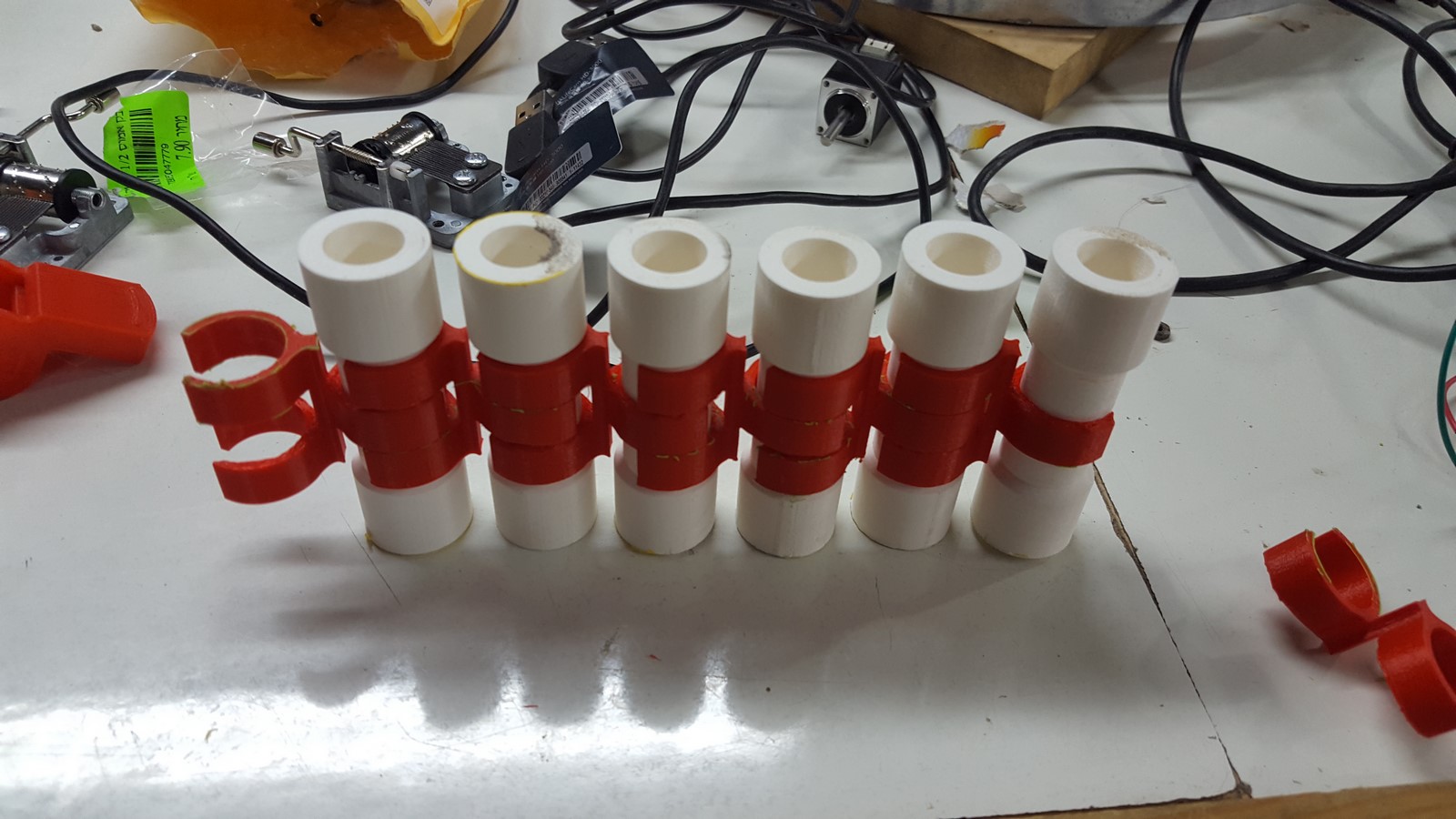
Almost all the parts can be 3D printed and are public files on Onshape.
One of our first testing was to print many dart holders and check the dart-changing mechanism works
Finally we stripped the two webcams from their plastic case, put them in our own case so they won't move after calibration, and tried to shoot some Nerf darts (Also added a laser pointer for the fun!)
Face Recognition
I tried several face recognition algorithms, one of them was using a pre-trained neural network that can predict age and gender and use it to classify certain images. The problem was that I couldn't get it to work on real time data on 30 FPS camera stream. Eventually I used this Github repository which was the perfect solution and worked very good. It is based on the dlib libraries for computer vision and machine learning. You can find the implementation on my code. I tried several other algorithms but unfortunately didn't document everything so can not share.
After the project was working, it was standing as a demo for a few months on some exhibition. Unfortunately I didn't have any good videos from this exhibition. After a few months it wasn't active anymore and only after two years I took it back to my house, not sure if it was even still working.
Code
Since the code is from two years ago, I'll try my best to explain it here:
Arduino Code
First, I've written the class.h code which defines the motor class. Inside the motor class there are several functions:
- Class constructor - Here you can define all the motors pinouts, and ID.
moveStepMotor- Move motor to a certain direction, for a certain delay (was used in a former project)setCommand- Set motor's command as a desired encoder value.moveMotorCCW,moveMotorCW,moveMotorStop- Move motor CCW or CW, or stop.moveMotorPID- Move motor according to PID result.moveMotor- General function which reads the PID result, the current encoder values and decides the needed operation (Uses all the above functions).getState- return the current state of the motor (CW, CCW, stop).
The main code pipeline is as I described before. I will explain here some of the important parts:
In the setup() function:
attachInterrupt(Motor0INT, readEncoder0, CHANGE); //attach interrupt to PIN 2
attachInterrupt(Motor1INT, readEncoder1, CHANGE); //attach interrupt to PIN 3
attachInterrupt(Motor2INT, readEncoder2, CHANGE); //attach interrupt to PIN 21
attachInterrupt(shootButtonInt, shootCommand, FALLING); //attach interrupt to PIN 20
Attaching the interrupts to each motor and shooting button to receive real-time accurate results.
In the loop() function:
  if ((shootFlag) && (readyToShoot)) {
    shoot();
    shootFlag = false;
    readyToShoot = false;
    commandEnc = commandEnc + MOTOR_C_QRT_RND;
  }
Shoot, only after making sure the dart is in the right position. Afterwards command the dart changing motor to switch darts.
  Setpoint0 = (double)commandAz;
  Input0 = counts0;   //<===========================
  myPID0.Compute();
  double nOutput0 = constrain(map(Output0, -PIDLIM*k_att0, PIDLIM*k_att0, -255, 255),-255,255);
  motor0.moveMotor(nOutput0); //<===========================
Compute PID for each motor, and give the motor the needed command.
readEncoder0- Update the current encoder value.serialEvent- Serial interrupt, for retrieving information coming from the computer.
Computer Code
On this code, there are three threads running in parallel:
cameras_handle- Retrieve images from the webcams and execute face detection, keeping the coordinates of the detected face.face_recognition_handle- Updated when there is a new face detection and try to recognize who is this face belongs to using a pre-trained database of encoded faces.oculus_handle- Receives quaternion data (Head angels) from the Oculus VR kit and sends the needed commands to the Arduino.
Two Years Later - The Geekcon project
General description
On Geekcon, you have only two days to work on your project, and the project should be something fun and useless. The idea of this project started when I wanted to make two things over the Geekcon weekend:
- Try to revive the shooter we have built two years ago. Wasn't sure if any wires were torn or if the motors still working properly.
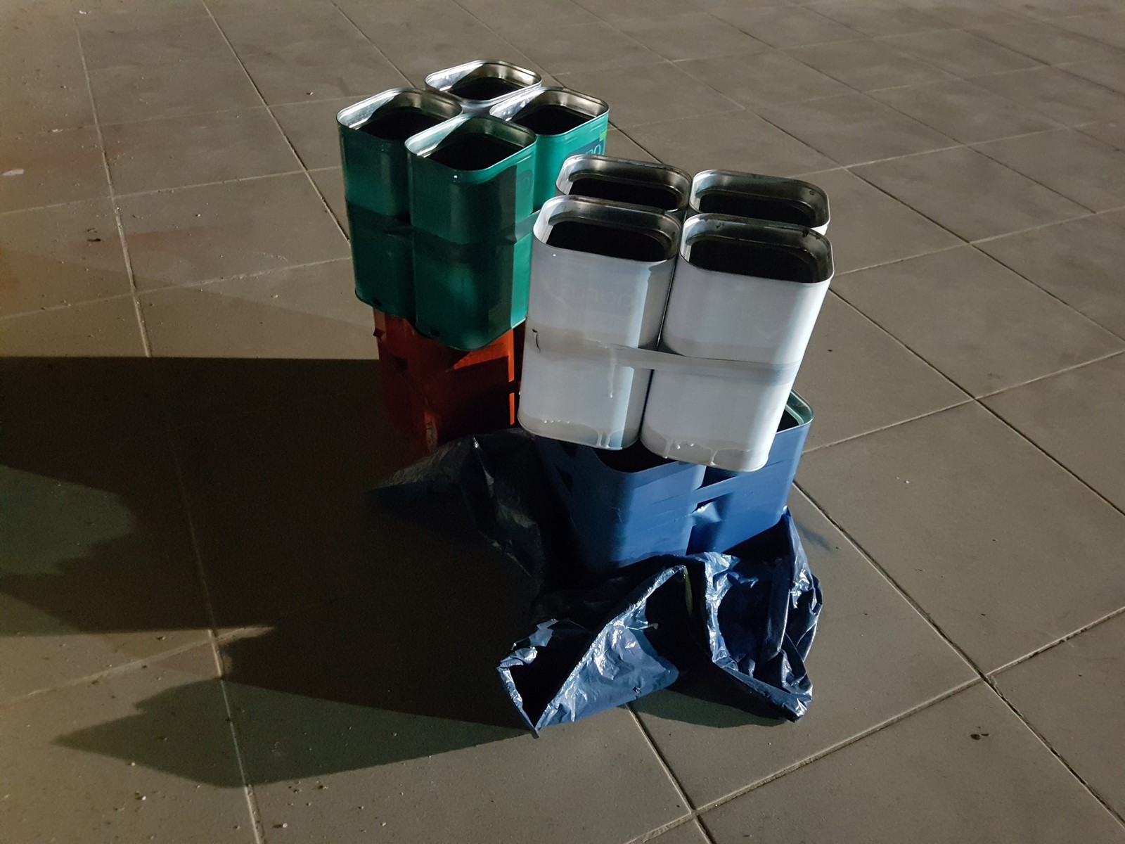
- Since my daughter was born, I have kept many empty metal cans which had originally contained baby formula. I didn't really know what I want to do with them, but I knew I should use them for something on this event.
So we came up with the idea of re-purposing the shooter as an automated shooter, which can track targets and shoot at them. The targets were made with addressable LEDs inside the metal cans and also using a new code, which uses a video stream from a high speed camera and detects if a dart entered a can - If so, it commands to changed the can color.
Compared to the old project, the new project had some new components:
- Computer 1 communicating with the shooter as before, but with a new code.
- Computer 2 communicating with the targets and a high speed camera
The new pipeline of the code on computer 1 was as follows:
- Receives video stream from a the shooter's cameras (Only one was needed this time).
- Receives a tracking command from the user, which means a pixel in the image which we want the shooter to target. The idea was to use this code later on to make the shooter automated but we didn't get to it.
- Tracking: If the image changes, it finds the location of the old pixel on the new image.
- Calculates the error between the pixel and the center of the image (or to where the dart eventually goes which was mostly on the lower part of the image).
- Transforms the pixels error to the physical angles error (pitch and yaw).
- Transforms the physical angles error to encoders' values.
- Sends a new command to the the shooter.
Executing the described pipeline creates a semi-automatic Nerf-gun shooter which is really nice since it actually works pretty well!
The pipeline of the new code on computer 2 was as follows (I wrote a more detailed explanation under the code part later on):
- On code initialization: Automatically Determine all the targets' locations.
- Check only the Region Of Interest (ROI) of the targets' locations.
- Find changes in these ROIs due to dart hit.
- In case there was a hit - Send a specific color command to the targets' computer (ESP8266)
On the ESP8266 the pipeline is very simple:
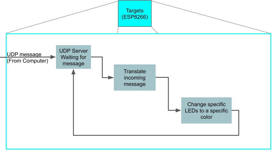
- A UDP server is set-up, waiting for messages.
- When a message arrived - Translate the protocol to a command.
- Change the desired target to a different color.
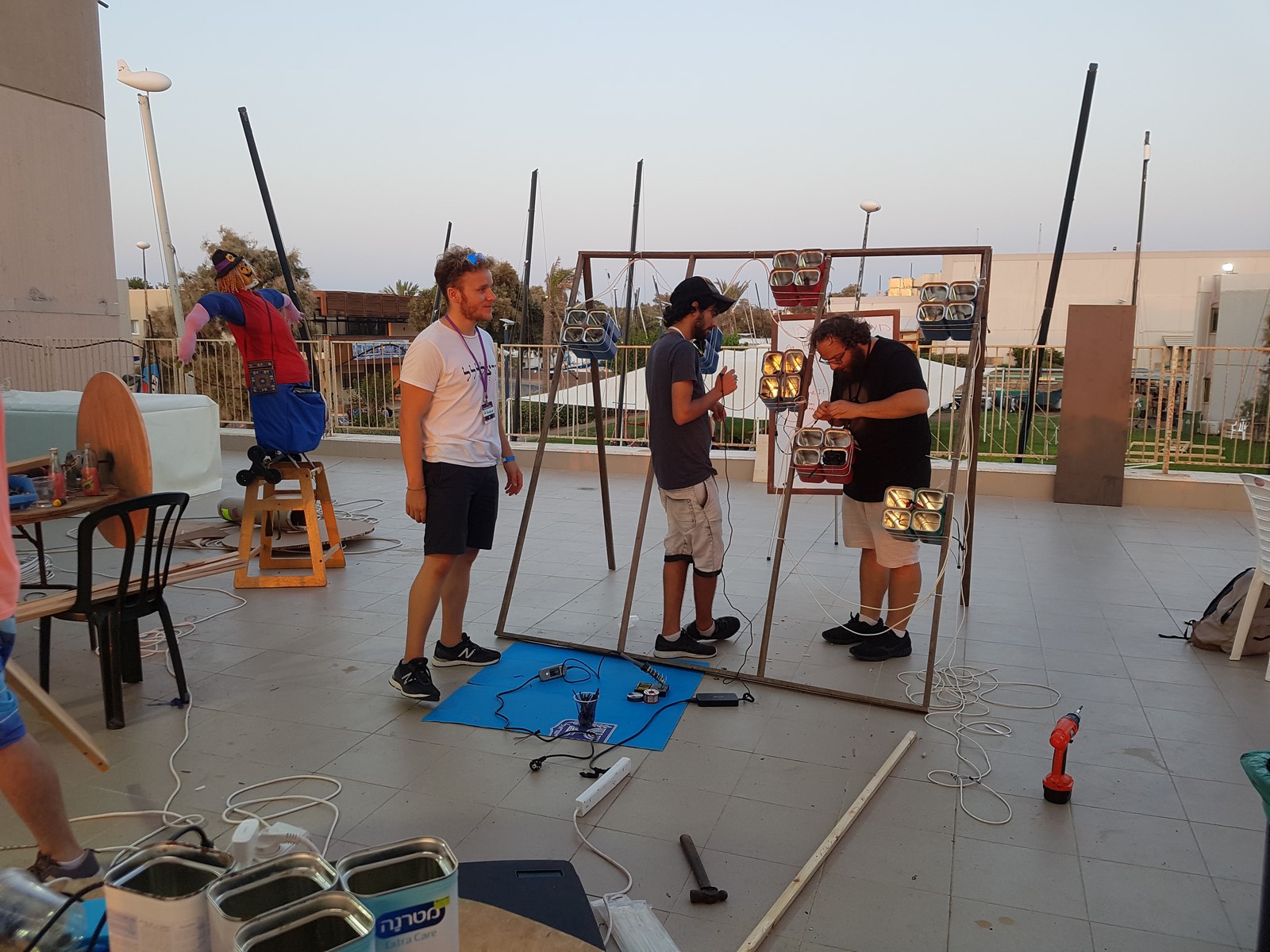
Build Up
Since the shooter hasn't been used for two years, we spend a lot of time on reviving it during that weekend. While doing so, we found some replacement to things which didn't work properly such as the air valve, the camera and one of the motors. This was mostly ad-hoc solutions so I have nothing to write about them here.
The targets construction on the other hand was something we built from scratch during that weekend. We started by taking the baby formula cans and check how well could they act as targets. We taped together four cans, then made holes on the lower part of each can and inserted four addressable LEDs in each can. The next step was to connect it to an arduino and check how well the colors look from far away:
After we found a good location for the LEDs, we spray-painted the cans in different colors.
Then, we built a wooden construction from several boards, and tied all the cans to the construction.
Next, we soldered all the leds and tested everything works properly:
Last, we connected the ESP8266 with the updated code, and from here we could remotely control all the LEDs.
Then it was time for integration, and from that point we started testing our entire project together. First was the high speed camera and the target detection. In the next video you can see the Init part on computer 2 which automatically detect all the target locations.
And this is what happens when a dart hits a target:
Next, we calibrate the tracking and shooting of the new program on computer 1. Here is how the tracking looked like:
And the shooting:
Finally, everything was working more or less. It wasn't working so great but had very nice results for only two days of work. darts sometimes got stack in the round-barrel, the tracking wasn't always perfect, but it was already really fun to play with it.
Code Notes
Computer 1 (Shooter)
We started from the VR shooter code I described earlier and changed it a bit to work as follows:
- The thread which received angles measurements from the Oculus VR kit and sent it to the arduino stayed almost the same, just now it was receiving desired angles from a new thread.
- A new camera thread was added, which started being relevant after we double click on a selected pixel in our video stream. The code takes a square of 10X10 pixels around the selected pixel and tries to find all those pixel on a new image in the stream using an optical flow algorithm (
cv2.calcOpticalFlowPyrLK). After finding the new location, it calculates the error from the middle of the image, translate it to the desired angles and continue to the next frame.
Computer 2 (High Speed Camera)
I'm adding some code explanations by NotAMacUser. We have several classes in play here:
Camera- This is just a class that takes care of handling the camera input.TargetDetector- Each of the targets has this class. It has the ability to detect a hit using the "diff" image from the camera in a certain ROI (So basically it's a simple change detector). In order to do so, we perform background subtraction and see if the absolute difference of the changes in the target polygon is more than a threshold which was chosen by trial and error. Note: The threshold can be changed if you work under a 50Hz flickering light or in the open when the sun or clouds locations change.
        mask = np.zeros(self.cam.last_frame.shape)
        mask2 = cv2.fillConvexPoly(mask, self.target_poly, (1, 1, 1), 1).astype(np.bool)

        target_diff = self.cam.getdiff() * mask2
        thresh = np.sum(np.abs(target_diff.astype('float32')) > 50)
After these lines we have the sum of all the pixels that changed by more than the threshold. If it's more than the size of a Nerf dart we can say that there was a detection
         if thresh > 5:
            print('target #{}, 1st detection: {}, {}'.format(self.detector_id, thresh,np.max(np.abs(target_diff.astype('float32')))))
LedControl- This class is basically the game-rendering part. In our game we were just sending commands to change the targets' leds color. if there was a hit we changed the color of the target from green to red. The communication was done through UDP to the ESP8266 controller which was connected to the LEDs.
The rest of the code on computer 2 is the game-engine. In order to define the game board we measured the targets construction with a ruler and used 4 points on the surface of the wooden stage to geometrically find all of the targets' locations. It worked really well because instead of trying to detect the targets using complicated computer vision techniques we just used plain-old geometry.
So you choose 4 points on the wooden stage and write down the $[x,y,z]$ coordinated according to some chosen relative $[0,0,0]$ point (Which could have been outside the wooden stage and sometimes it is useful this way, for instance if you put markers on a pen but you want the tip of the pen to be the $[0,0,0]$). For example:
box_world_pts = np.array([[0, 0, 0],
                          [1.96, 0, 0],
                          [1.96, 1.48, 0],
                          [0, 1.15, 0]], dtype='float32')
The values are in meters but it doesn't matter what you choose as long as you are consistent. Then we choose 4 points on top of the video:
After we have the points from real-world coordinates (which we measured with the ruler) and the 2D image-coordinates points (which we choose on the image) we can use the OpenCV solvePnP algorithm which finds an object pose from 3D-2D point correspondences. In our example we choose 4 points which is the minimum needed but the more the better. If you have many points you can use solvePnPRansac which uses the RANSAC algorithm to remove outliers and suggests a better solution.
ret, rvec, tvec = cv2.solvePnP(box_world_pts, temp_pts.astype('float32'), mtx, dist, flags=cv2.SOLVEPNP_P3P)
This process should be done only once since we assume the camera and the wooden construction are static so this really simplifies everything.
Once we know the relative position of the camera to the construction we can calculate the locations of all the targets since we know their real-world location. All we need to do is to re-project the points from the real-world coordinate system to the camera coordinate system. We can do this using the cv2.projectPoints function:
for target in target_list:
   box1_poly, _ = cv2.projectPoints(target.reshape(-1, 3), rvec, tvec, mtx, dist)
                detectors_list.append(TargetDetector(camera, box1_poly.astype('int32')[:, 0, :], len(detectors_list)))
   box_poly_list.append(box1_poly.astype('int32')[:, 0, :])
and we get the position of the 4 points of the rectangle that constitutes a target, which can be fed to the TargetDetector (Which uses those points to create a polygon that would be sampled every frame).
ESP8266 (Targets)
This code is very simple if you combine two code samples which are part of the libraries of WiFiUdp.h and Adafruit_NeoPixel.h. The samples are:
- Controlling WS2812 using ESP8266.
- Setting up a UDP server.
On the setup() function:
  WiFi.begin(ssid, password);
  UDPTestServer.begin(UDPPort);
Connecting to WiFi and setting up UDP server.
  strip.begin();           // INITIALIZE NeoPixel strip object (REQUIRED)
  strip.show();            // Turn OFF all pixels ASAP
  strip.setBrightness(255); // Set BRIGHTNESS to about 1/5 (max = 255)
Initializing the LED strip.
on the loop() function we call handleUDPServer() which reads the UDP protocol and executing the requested command. The protocol we came up with was very simple, 5 bytes for each target. For instance, if we receive a message size of 30 bytes, we will know there are 6 commands for 6 different boxes. The 5 bytes are used for:
- Target ID
- General OpCode
- Red Color
- Green Color
- Blue Color
Basically the "OpCode" was not needed but we thought that later-on it will be cool if we add some cool animations instead of a single color when you hit a target so we left this option open.
The handleUDPServer() function executes a for loop, such that for each target it reads the requested command and uses the turn_on_box() function to change its color.
#
So that's summarizes the entire process of two really fun projects. I hope some of my references will help people to build some cool toys out of Nerf guns, and come join us to Geekcon 2020!
AA