In today’s blog, I am going to show you the easy way to interface 7-segment displays – Using the MAX7219. Each 7219 chip can be used to interface eight 7-segment digits, or 64 individual LEDs.
Previously, in part 1 of my blog posting Programming a 7-segment Display, using just Arduino digital pins (the hard way), we had demonstrated how to hook up a pair of 7-segment displays to an Arduino, treating each individual segment as a separate LED. There was a bit of tricky logic to translate each digit into the segments A, B, C, D, E, F, G plus additional logic to turn the digital pins on or off. Although I tried to code it as efficiently as possible, the logic may have been difficult to understand.
Also, constructing the project was fairly tedious, with dozens of resistors and hook-up wires.
Instead, lets do this the easy way. A typical MAX7219 module comprised of a single MAX7219 chip and eight 7-segment displays. It looks like this:
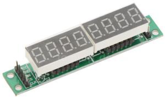
This module can be purchased for a dollar or two from eBay or Ali Express. These modules interface to the Arduino using only 3 digit signals. Therefore, they are super easy to wire, and, as you will see, easy to program.
How is the MAX7219 Controlled by the Arduino?
Let’s start with the DATASHEET. Download it here:
max7219_datasheet.pdf
Like many driver chips, the MAX7219 has a register model. The application processor – the Arduino in our case – writes values into the MAX7219 registers. Thus, the MAX7219 register values control the operation of the chip. All interactions with the chip are defined in terms of setting one or more registers.
The MAX7219 has relatively few registers. We can understand how to do all operations by studying this register set. Pages 7 through 10 of the datasheet explain, sometimes in excruciating detail, all about this register set. However, a simple summary of the register semantics will explain the chip sufficiently to get you going:
| Register Name | Register Address | Meaning |
|---|---|---|
| DIGIT0 | 1 | Right-most digit value |
| DIGIT1 | 2 | Next digit value |
| DIGIT2 | 3 | digit value |
| DIGIT3 | 4 | digit value |
| DIGIT4 | 5 | digit value |
| DIGIT5 | 6 | digit value |
| DIGIT6 | 7 | digit value |
| DIGIT7 | 8 | Left-most digit value |
| Decode Mode | 9 | With 1 bit for each of digit 0-7; if set, interpret the digit as a BCD digit to display. If not set, the bits in the digit register directly light up the 7-segments |
| Intensity | 0x0A | The proportion of time the display segments are on and how bright is the display |
| Scan Limit | 0x0B | How many of DIGIT0 through DIGIT7 are displayed |
| Shutdown | 0x0C | If 0, turn display off; If 1, turn display on |
| Display Test | 0x0F | If 0, turn test mode off; If 1, turn test mode on |
So, creating any display is simply setting these registers with values.
An example of setting the Registers
Here is an example. To write a 3-digit value “123” into the right-most three digits, we do the following
- Set the SHUTDOWN register to off
- Set the DIGIT0 register to “3”
- Set the DIGIT1 register to “2”
- Set the DIGIT2 register to “1”
- Set the DECODEMODE register to binary 00000111, so the 3 right-most digits are decoded.
- Set the SCANLIMIT register to 2, so digits 0, 1, 2 and 3 are displayed
- Set the SHUTDOWN register to on, to turn the display back on
That’s it! We can certainly create an Arduino-C function for these simple steps.
How do we communicate with the MAX7219 from the Arduino? How do we send these “set register” commands?
The MAX7219 is serially interfaced to the Arduino. This means that the data is sent serially or one bit at a time. Although this sounds complicated, it is really quite straight forward.
Figure 1, on page 6 of the datasheet, describes sending a register set command, as sending the serial data like this:
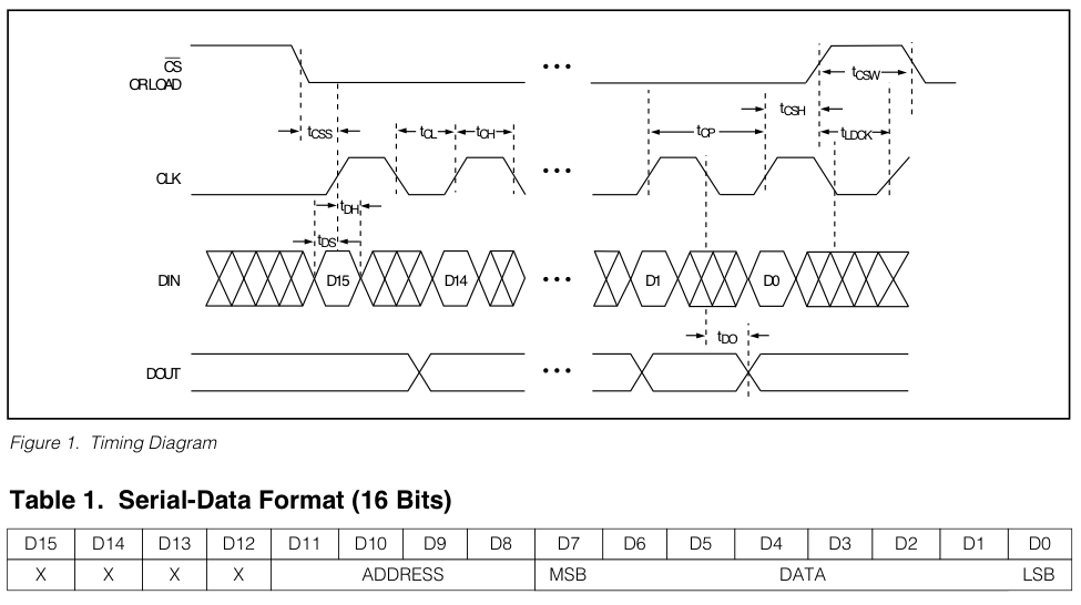
Someone who has no experience looking at these Timing Diagrams will be lost. However, not to worry. The Timing Diagram shows an industry-standard method of serial data transfer. In Arduino C, we implement this as follows:
// ... write a value into a max7219 register
// See MAX7219 Datasheet, Table 1, page 6
void set_register(byte reg, byte value)
{
    digitalWrite(MAX7219_CS, LOW);
    shiftOut(MAX7219_DIN, MAX7219_CLK, MSBFIRST, reg);
    shiftOut(MAX7219_DIN, MAX7219_CLK, MSBFIRST, value);
    digitalWrite(MAX7219_CS, HIGH);
}
It is simply those 4 lines of code. The Arduino-C built-in function shiftOut() does the magic of serially sending the data on pin DIN one bit at a time, while cycling the CLK pin.
The Timing Diagram above shows all sorts of timing constraints – however, not to worry, the shiftOut() function is fully compliant to those timing constraints. Also, the Timing Diagram specifies that the first bit transferred is D15, then D14, … finally D1 and D0. This is accomplished with the keyword MSBFIRST in the call to shiftOut().
Putting this together into a higher-level function to display the Time
Now, using this set_register() function, let’s create a function called display_time() which will take the time in a string, such as “18:35:04” (or hh:mm:ss format), and display it like this:
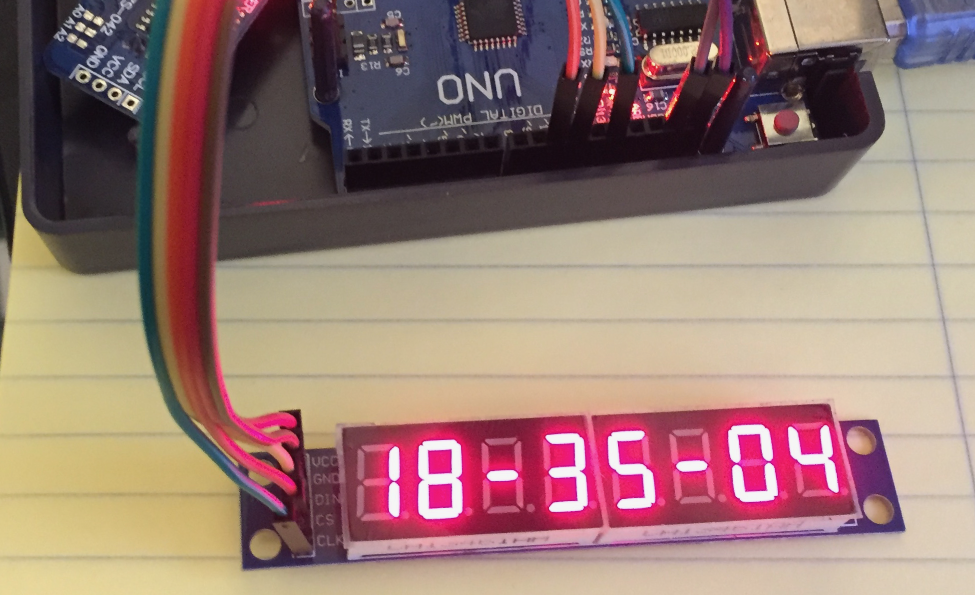
The code to accomplish this is as follows.
// ... display the TIME on the 7-segment display
void displayTime(String timeString)
{
    set_register(MAX7219_REG_SHUTDOWN, OFF);      // turn off display
    set_register(MAX7219_REG_SCANLIMIT, 7);       // limit to 8 digits
    set_register(MAX7219_REG_DECODE, 0b11111111); // decode all digits

    set_register(1, timeString.charAt(7));
    set_register(2, timeString.charAt(6));
    set_register(3, timeString.charAt(5));
    set_register(4, timeString.charAt(4));
    set_register(5, timeString.charAt(3));
    set_register(6, timeString.charAt(2));
    set_register(7, timeString.charAt(1));
    set_register(8, timeString.charAt(0));

    set_register(MAX7219_REG_SHUTDOWN, ON);       // Turn on display
}
I think this is very straight forward code.
The only difficult aspect of writing this function was the order of setting the registers. Through some trial and error, we discovered that the display was more stable if we modified the SCANLIMIT and DECODE registers only when the display was off, or in shutdown mode. Therefore, this function begins with turning off the display and ends with turning the display back on.
How do I create a character display other than a numeral?
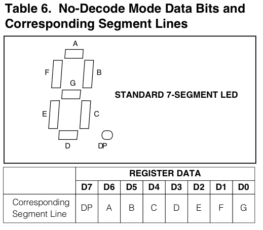
In our application, we will have the requirement to display a Temperature either in Celsius or Fahrenheit, like this:
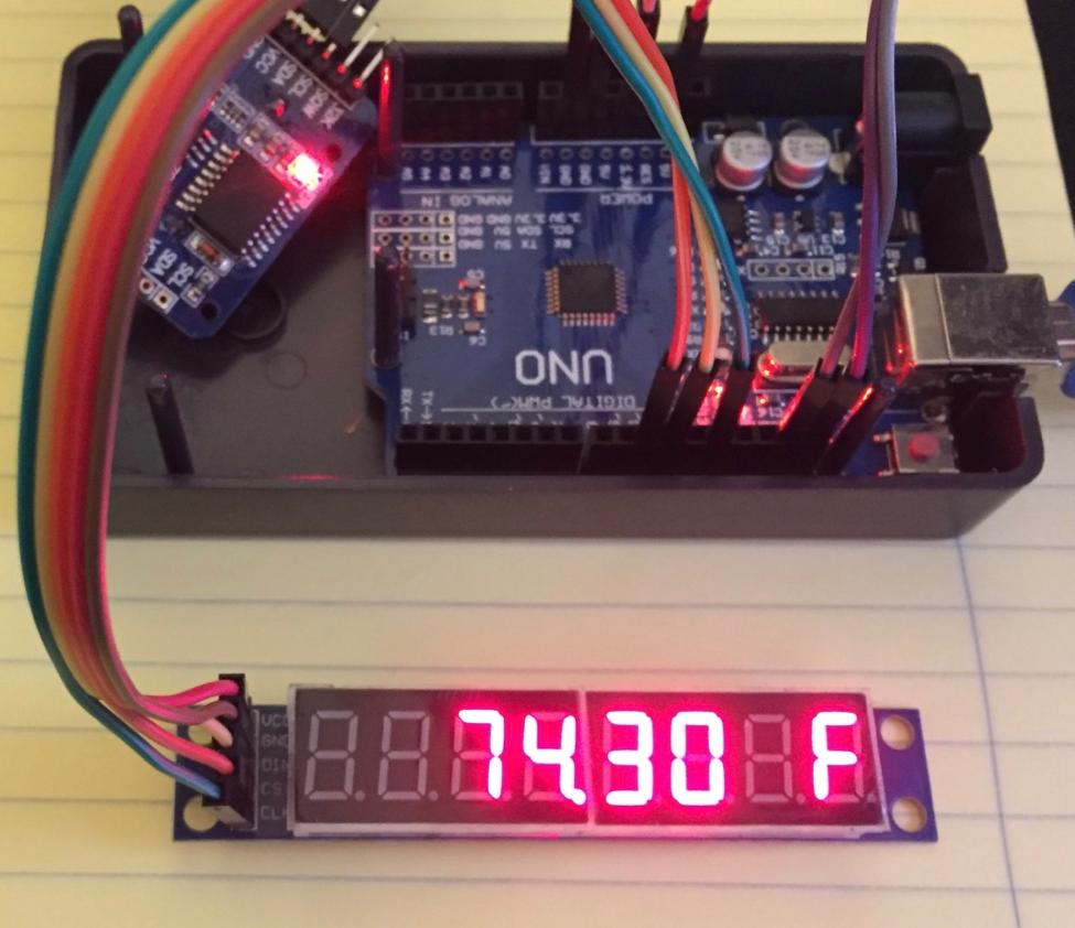
To create a character C or the character F, we have to use the no-decode mode of the MAX7219. In this case, the segments, A, B, C, D, E, F and G are controlled individually. We can refer to Table 6, from Page 8 of the data sheet:
In order to display the letter C, we light segments A, F, E, D. For the letter F, we light segments A, F, G, E. Here is a table to show how we construct the binary values representing symbols C and F:
| Dp | A | B | C | D | E | F | G | |
|---|---|---|---|---|---|---|---|---|
| Symbol C | 0 | 1 | 0 | 0 | 1 | 1 | 1 | 0 |
| Symbol F | 0 | 1 | 0 | 0 | 0 | 1 | 1 | 1 |
In Arduino-C, we can express these values as const bytes:
const byte C  = 0b01001110;
const byte F  = 0b01000111;
And the line of code to set DIGIT0 to C would be
set_register(0x01, C);
or to set DIGIT0 to F would be
set_register(0x01, F);
Once we have figured out that little trick, we are ready to write the function to display the Temperature in the 7-segment display:
// ... display the TEMP on the 7-segment display
void displayTemp(String tempString, char C_or_F )
{
    set_register(MAX7219_REG_SHUTDOWN, OFF);      // turn off display
    set_register(MAX7219_REG_SCANLIMIT, 5);       // limit to 6 digits
    set_register(MAX7219_REG_DECODE, 0b00111100); // decode 4 digits

    set_register(1, C_or_F);
    set_register(2, 0);                           // blank
    set_register(3, tempString.charAt(4));
    set_register(4, tempString.charAt(3));
    set_register(5, tempString.charAt(1) | DP);   // plus dec. point
    set_register(6, tempString.charAt(0));

    set_register(MAX7219_REG_SHUTDOWN, ON);       // Turn On display
}
A Useful Application for the Max7219 module
Now we are ready to describe the entire application. The purpose of the application is to display the date, time and temperature, using the 7-segment display. The date, time and temperature are read from the DS3231 chip, which is attached to the Arduino’s I2C bus.
We are going to grab a DS3231 driver from the Arduino contributed libraries. I like the one at rinkydink.com. After installing it our our personal Arduino libraries, we import it into our code using
#include <DS3231.h> // import library from rinkydink.com
We will use the methods
String rtc.getDateStr()
String rtc.getTimeStr()
Float rtc.getTemp()
which return those values. We are not going to describe the DS3231 chip and this library in detail at this time, although, perhaps I will in another blog. We are using this chip as a sort of “black-box”, which magically returns either the Date, the Time, or the current Temperature (of the DS3231 chip itself).
Because the 8-digit display is limited, we have to make design decisions as to how to present this information. My WhatIMadeToday partner Mike gave me the requirements:
- Display the DATE for a few seconds in the format: DD.MM.YYYY
- Then display the TIME for a few seconds in the format HH-MM-SS
- Then display the Temperature, first in Celsius, then in Fahrenheit for a few seconds.
- And repeat.
Here is the entire Arduino Application:
/**
 * @file        max7219_7segment_date_time_temp.c
 *
 * @brief       view DATE/TIME/TEMPERATURE using an 8-digit
 *              7-Segment display
 *
 * @history     Feb 6th, 2017
 *
 * @author      Allan Schwartz <allans@CodeValue.net>
 *              Michael Diamond <m.diamond.il@gmail.com>
 *
 * @notes       The following Arduino Pins are attached:
 *
 *              name    Arduino   7 Segment display
 *              -----   ----      -----
 *                      +5V       VCC
 *                      GND       GND
 *              DIN     D11/MOSI  DIN
 *              CS      D10/SS    CS
 *              CLK     D13/SCK   CLK
 *
 *              name    Arduino   RTC module
 *              -----   ----      -----
 *                      nc        32K
 *                      nc        SQW
 *              SCL     SCL/A5    SCL
 *              SDA     SDA/A4    SDA
 *                      3v3       VCC
 *                      GND       GND
 */

#include <DS3231.h>           // import library from rinkydink.com

// define pins attached to MAX7219 (and also see notes above)
#define MAX7219_DIN           11
#define MAX7219_CS            10
#define MAX7219_CLK           13

// enumerate the MAX7219 registers
// See MAX7219 Datasheet, Table 2, page 7
enum {  MAX7219_REG_DECODE    = 0x09,
        MAX7219_REG_INTENSITY = 0x0A,
        MAX7219_REG_SCANLIMIT = 0x0B,
        MAX7219_REG_SHUTDOWN  = 0x0C,
        MAX7219_REG_DISPTEST  = 0x0F };

// enumerate the SHUTDOWN modes
// See MAX7219 Datasheet, Table 3, page 7
enum  { OFF = 0,
        ON  = 1 };

const byte DP = 0b10000000;
const byte C  = 0b01001110;
const byte F  = 0b01000111;


// create an instance of the DS3231 called 'rtc',
// and specify the hardware interface PINS
DS3231 rtc(SDA, SCL);


// ... setup code here, to run once
void setup()
{
    // initialize the serial port:
    Serial.begin(115200);           // initialize serial communication
    Serial.println("max7219_7segment_date_time_temp");

    // define type of pin
    pinMode(MAX7219_DIN, OUTPUT);   // serial data-in
    pinMode(MAX7219_CS, OUTPUT);    // chip-select, active low
    pinMode(MAX7219_CLK, OUTPUT);   // serial clock
    digitalWrite(MAX7219_CS, HIGH);

    resetDisplay();                 // reset the MAX2719 display

    rtc.begin();                    // init. the DS3231 RTC interface

    // Uncomment the following lines to set the RTC
    //rtc.setDOW(WEDNESDAY);        // Set Day-of-Week to WEDNESDAY
    //rtc.setTime(16, 20, 0);       // Set the time to 4:20pm
    //rtc.setDate(8, 2, 2017);      // Set the date to 8-Feb-2017
}


void loop()
{
    String str;                     // scratch or working string

    // ... display Date, dd.mm.yyyy
    // read the date as a string from the RTC
    str = rtc.getDateStr(FORMAT_LONG);
    Serial.println(str);            // debug
    displayDate(str);               // display on the 7-segment
    delay(6000);

    // ... display Time, hh-mm-ss
    for ( int i = 0; i < 6; i++ ) {
        // read the time as a string from the RTC
        str = rtc.getTimeStr(FORMAT_LONG);
        Serial.println(str);        // debug
        displayTime(str);           // display on the 7-segment
        delay(1000);
    }

    // ... display Temperature in Celsius, xx.xx C
    // read the temperature, as a float, from the RTC
    float t = rtc.getTemp();
    str = String(t, 2);             // format that value
    Serial.println(str);            // debug
    displayTemp(str, C);            // display on the 7-segment
    delay(3000);

    // ... display Temperature in Fahrenheit, xx.xx F
    t = t * 1.8 + 32.0;             // convert the value to Fahrenheit
    str = String(t, 1);             // format that value
    Serial.println(str);            // debug
    displayTemp(str, F);            // display on the 7-segment
    delay(3000);
}


// ... write a value into a max7219 register
// See MAX7219 Datasheet, Table 1, page 6
void set_register(byte reg, byte value)
{
    digitalWrite(MAX7219_CS, LOW);
    shiftOut(MAX7219_DIN, MAX7219_CLK, MSBFIRST, reg);
    shiftOut(MAX7219_DIN, MAX7219_CLK, MSBFIRST, value);
    digitalWrite(MAX7219_CS, HIGH);
}


// ... reset the max7219 chip
void resetDisplay()
{
    set_register(MAX7219_REG_SHUTDOWN, OFF);   // turn off display
    set_register(MAX7219_REG_DISPTEST, OFF);   // turn off test mode
    set_register(MAX7219_REG_INTENSITY, 0x0D); // display intensity
}


// ... display the DATE on the 7-segment display
void displayDate(String dateString)
{
    set_register(MAX7219_REG_SHUTDOWN, OFF);  // turn off display
    set_register(MAX7219_REG_SCANLIMIT, 7);   // scan limit 8 digits
    set_register(MAX7219_REG_DECODE, 0b11111111); // decode all digits

    set_register(1, dateString.charAt(9));
    set_register(2, dateString.charAt(8));
    set_register(3, dateString.charAt(7));
    set_register(4, dateString.charAt(6));
    set_register(5, dateString.charAt(4) | DP); // plus decimal point
    set_register(6, dateString.charAt(3));
    set_register(7, dateString.charAt(1) | DP);
    set_register(8, dateString.charAt(0));

    set_register(MAX7219_REG_SHUTDOWN, ON);   // Turn on display
}


// ... display the TIME on the 7-segment display
void displayTime(String timeString)
{
    set_register(MAX7219_REG_SHUTDOWN, OFF);  // turn off display
    set_register(MAX7219_REG_SCANLIMIT, 7);   // scan limit 8 digits
    set_register(MAX7219_REG_DECODE, 0b11111111); // decode all digits

    set_register(1, timeString.charAt(7));
    set_register(2, timeString.charAt(6));
    set_register(3, timeString.charAt(5));
    set_register(4, timeString.charAt(4));
    set_register(5, timeString.charAt(3));
    set_register(6, timeString.charAt(2));
    set_register(7, timeString.charAt(1));
    set_register(8, timeString.charAt(0));

    set_register(MAX7219_REG_SHUTDOWN, ON);   // Turn on display
}


// ... display the TEMP on the 7-segment display
void displayTemp(String tempString, char C_or_F )
{
    set_register(MAX7219_REG_SHUTDOWN, OFF);  // turn off display
    set_register(MAX7219_REG_SCANLIMIT, 5);   // scan limit 6 digits
    set_register(MAX7219_REG_DECODE, 0b00111100); // decode 4 digits

    set_register(1, C_or_F);
    set_register(2, 0);                       // blank
    set_register(3, tempString.charAt(4));
    set_register(4, tempString.charAt(3));
    set_register(5, tempString.charAt(1) | DP); // plus decimal point
    set_register(6, tempString.charAt(0));

    set_register(MAX7219_REG_SHUTDOWN, ON);   // Turn On display
}
Enclosure
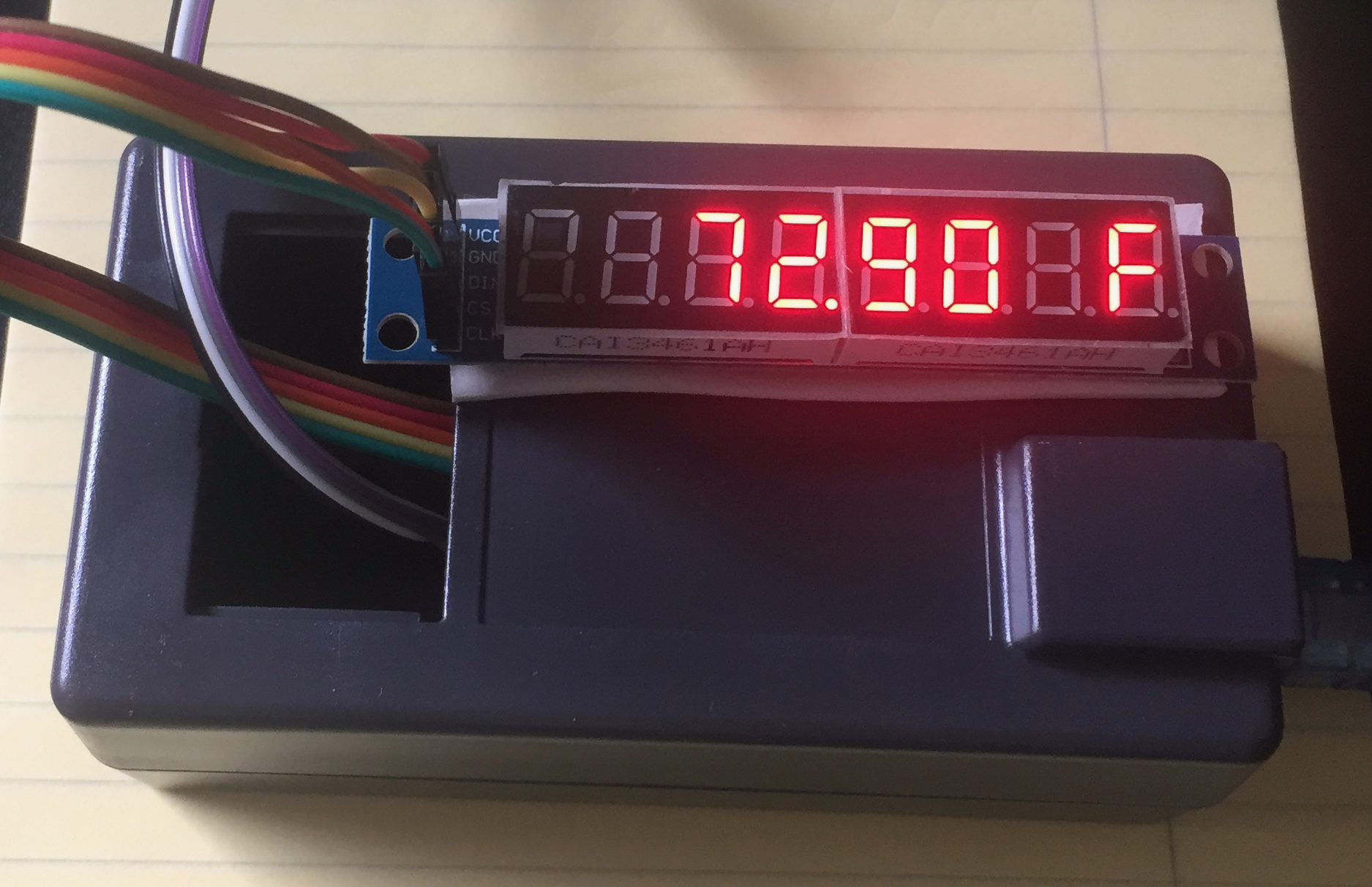
Here is my finished project box, with the display attached to outside of the enclosure with double-sided tape:
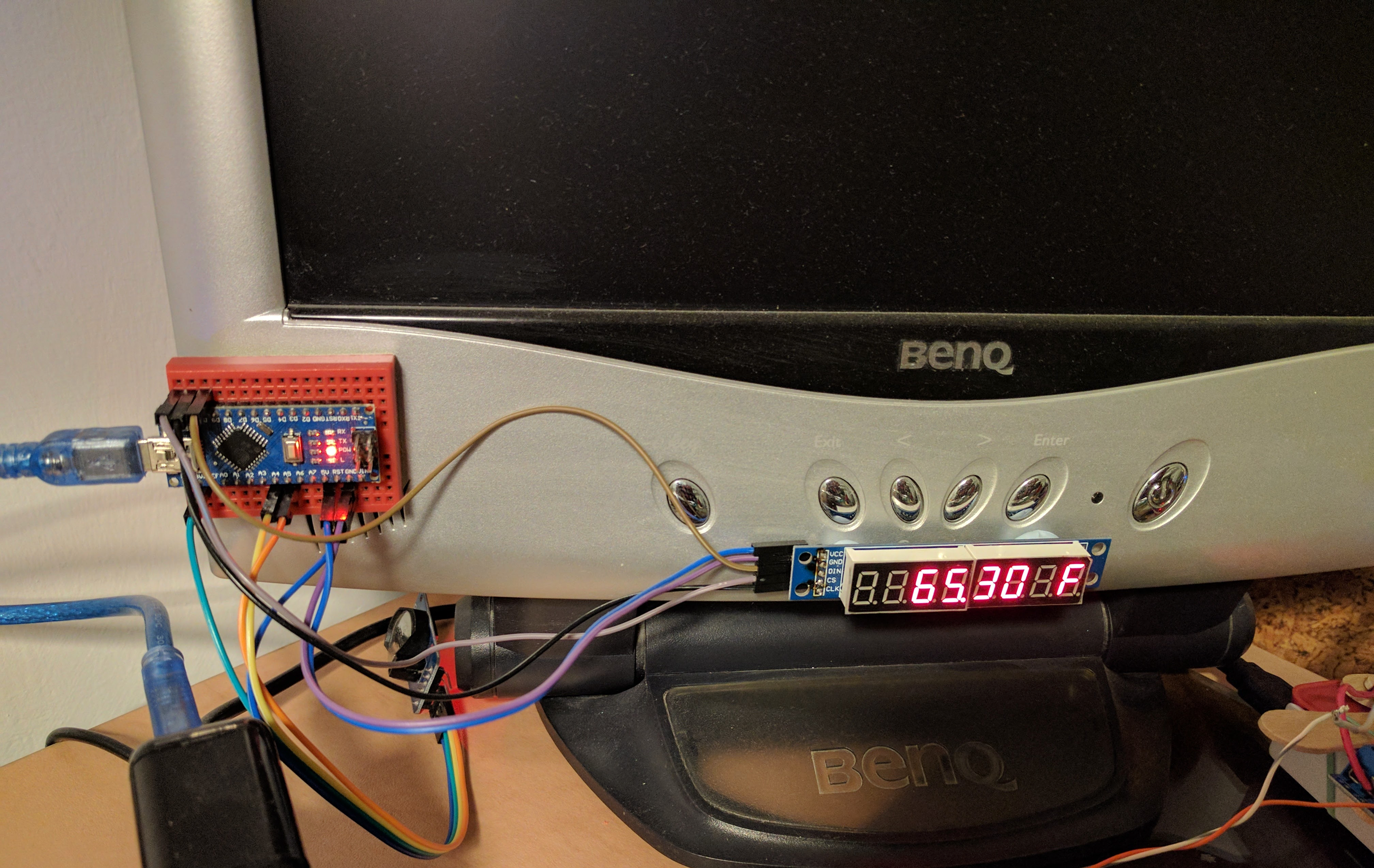
Mike has made several creative enclosures. Here is the display attached to his monitor:
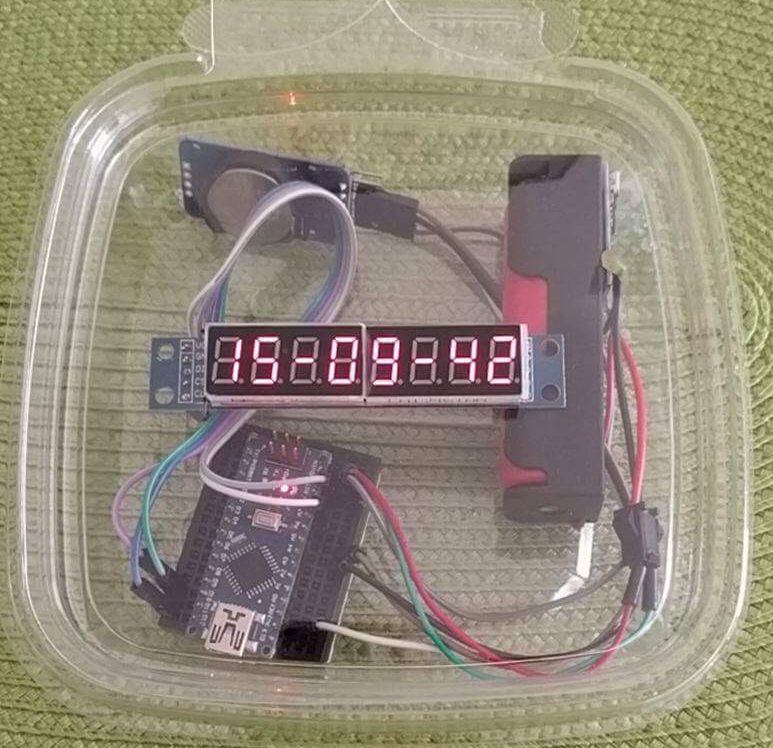
Here is one in a clear plastic box:
There is a lot you can do with this simple display. Have fun!