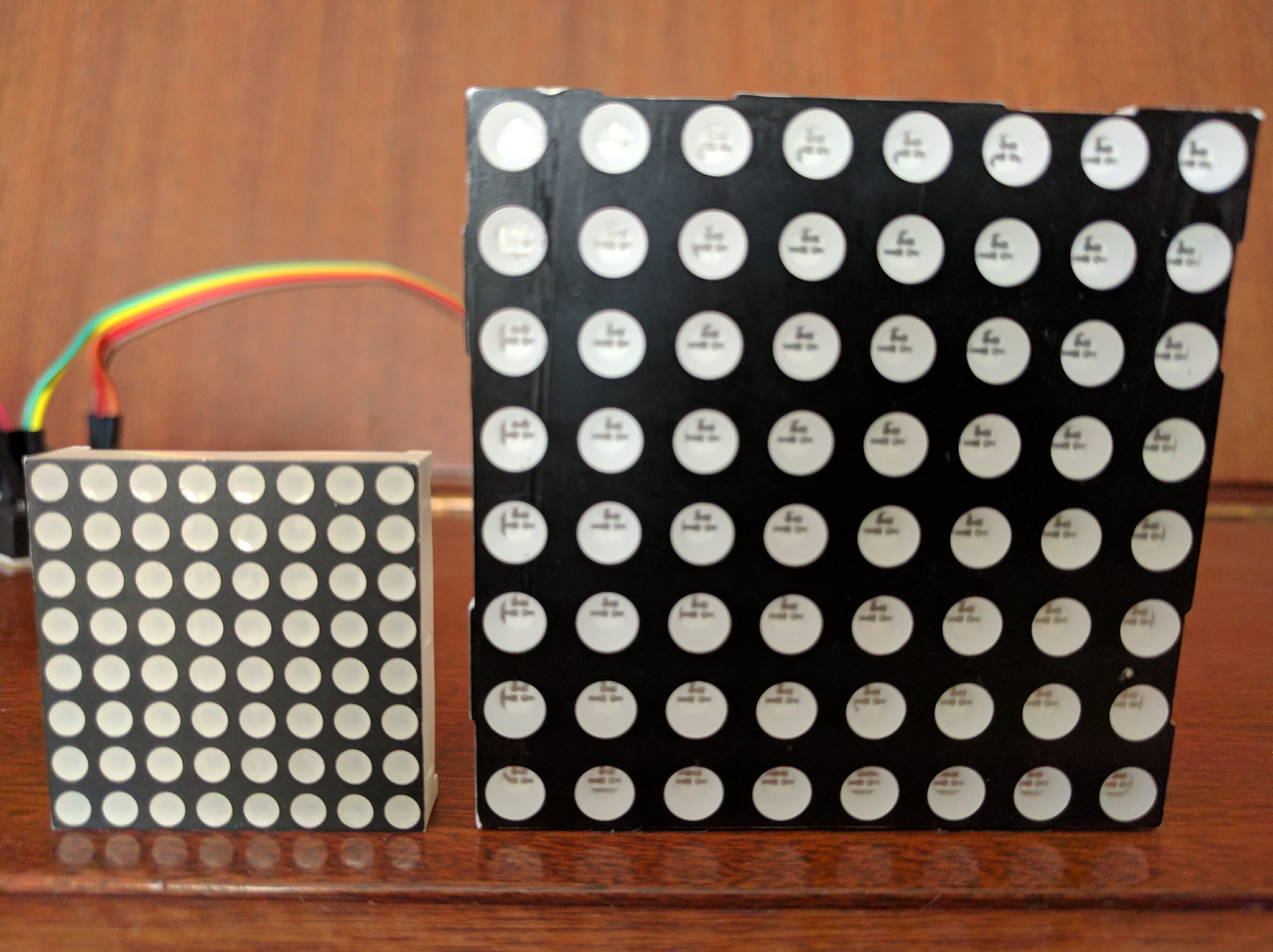
A couple of months ago, during a visit to foreign shores, I picked up an 8x8 LED matrix. What caught my eye was that it was about three times the size of matrixes I had at home - so anything displayed could be viewed from much further away. It was pretty cheap, so I threw it in my basket with all the other irresistible components we geeks enthuse about.
Date, Time & Temperature
At various locations around my house I have home-made clocks that display the date, time, and temperature running across little 8x8 LED matrix screens. Each unit is made with the following components:
- Cheap Chinese Arduino Nano
- DS3231 Real Time Clock (needed because without it, the Arduino doesn't know what time it is)
- Max 7219 8x8 LED Board
- 8 x 8 LED Matrix (1088AS)
Costing only about 3-4 dollars to make, I have them in several rooms, and being bright and visible from any angle, they're an ideal clock/thermometer. Perhaps I'll explain in a later post how they're made, but that's not the subject for today.
Pinning Things Down
Back in the shop, when I picked up my large matrix, I assumed all I'd need to do is attach its pins to the Max7219 board and all would be well.
It was only when I got it home that I realized that things wouldn't be so simple.
First, my new matrix had no markings on it at all. There was no way of identifying what it was. Second, I was alarmed to discover that instead of the 16 pins that were on my smaller matrix, this one had 24 pins. How on earth was I going to find which pins connect to what and how to get this thing working?
I went to the Internet and searched around. The only reference I could find to a 24-pin LED was a dual-colour unit that would display red and green. The shop got it wrong, I assumed - they sold me a dual-colour unit instead of a single colour unit.
But knowing this didn't solve my problem. How was I to know which pins controlled which pixels?
Whenever faced with a challenge like this, I always step back and give myself a couple of days to think about it. I came up with the idea of taking a CR2032 button battery, connecting a couple of wires to it, and prodding around the pins to see which ones light which pixel.
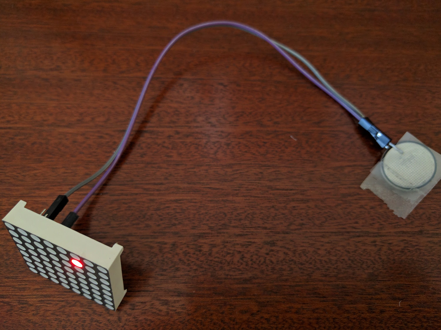
I made myself a little spreadsheet ready to map the red, green and common pins.
My experiment worked - but only in part. As I connected the pins to the battery, I didn't find any green LEDs. I quickly discovered that I was wrong; the shop didn't make a mistake. My matrix was red only. Eight of my 24 pins weren't connected to anything at all.
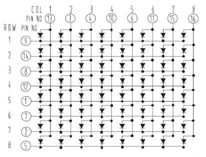
A pattern soon emerged as I studiously marked the pin numbers and pixels on my spreadsheet. With the pattern, I was able to Google images and find a diagram for my matrix.
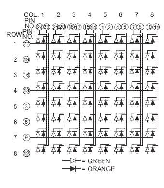
As you'll see, this is a diagram for a dual-coloured matrix, but in my case, only the red LEDs were connected.
Having now discovered that I had the same number of active pins (16) on each of my matrixes I thought it would be easy to make the connections and get things working.
Max 7219
Confident that I had things all worked out, I sat down to find which pin numbers in my small matrix corresponded to which pins on the large one. To do this, I had to map the small matrix too. This turned out to be easier as it was marked 1088AS. Here's the diagram I found for it on the web.
Looks pretty simple... but as usual, it's not...
You see, the physical pins on the matrixes are lined up in two rows. In the case of the small matrix, two rows of eight, and the large one, two rows of 12. These two rows refer to the pin numbers in the diagrams - which is quite different from the pixel locations and has no connection at all to the physical locations of the pins on the back of the matrix.
I thought I had all my numbers matched, so I connected the large matrix to the Max 7219 board and switched it on.
Nothing...
I re-examined everything, disconnecting all 16 pins from the matrix, and did it again; it's a fidgety process and I'd probably made a mistake.
When I switched on this time, I got four solid pixels and another eight flickering all over the place.
Again I disconnected. As I thought about it, I realized that the two rows on the Max 7219 board may not correspond to the pin numbers of the matrix. I was counting top to bottom on the left, then bottom to top on the right. Then I realized I don't actually know which way is up and which way is down!
To cut a long story short
For several hours I connected and disconnected, each time getting a different permutation of gibberish. Eventually I put it all aside. This needed careful thought and fiddling with wires wasn't helping.
It's the Orientation, Dummy
By the next day I'd realized my problem. I didn't know how the physical pins were numbered on either the small matrix or the large one, and I didn't know how they were numbered on the Max7219 board either.

It was then that it dawned on me that although scores of sites describe the 1088AS pixel layout, dimensions, and pin numbers - very few show the physical pins, their orientation, and numbering. This is key to getting things working and for some reason, few people cover it.
This is what I discovered:
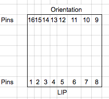
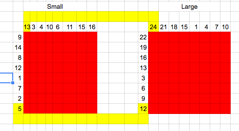
The small matrix has a little lip on one edge. When that lip is at the bottom, the physical pins are numbered like this:
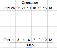
The large matrix has no up, down, left or right, so I simply put the pins at the same orientation as the smaller one, marking the bottom with a permanent marker. It's active pins were numbered like this:
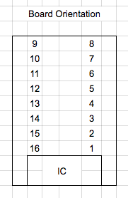
Finally, after quite a bit of searching, I discovered the Max7219 board's numbering. With the LED at the top, the pins are numbered like this:
Proper Mapping
So now that I had the proper numbering of the pins of all three components, it should be pretty easy to make the connections.
I created this spreadsheet diagram as a guide:
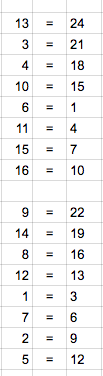
And from it I constructed this table:
Final Wiring
Now that I had all the pin numbers worked out, I connected the Arduino to the Max7219 board with the newly-mapped large LED and it burst into life!
But my troubles weren't over. Although the text and numbers flashed across the screen, everything was a mirror image of what it should be. Running from left to right as it should, all the letters and numbers were backwards.
Mirrored Image
I'd been at it for hours and I was ready to call it a day. I even harboured the thought of simply putting it in front of a mirror and leaving it as it was.
I spent about an hour reading forums about mirrored text, trying to work out how to reverse it. Some of them suggested running a script that would invert all of the matrix pixels, then re-flashing the reversed Arduino sketch. I even examined the sketch libraries trying to find - with my extremely limited programming skills - a command that would flip everything around.
I found nothing - so went to bed.
Finally Getting it Right
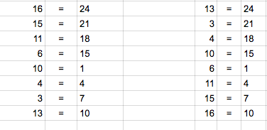
While flossing my teeth I had a brainstorm. Thinking in terms of rows and columns, I realised that my rows were right, but maybe my columns were reversed? If I inverted the column pins, perhaps my text would invert with it?
Next morning, I reversed the pins. Note the left column on the left table is the inverse of the left column on the right table.
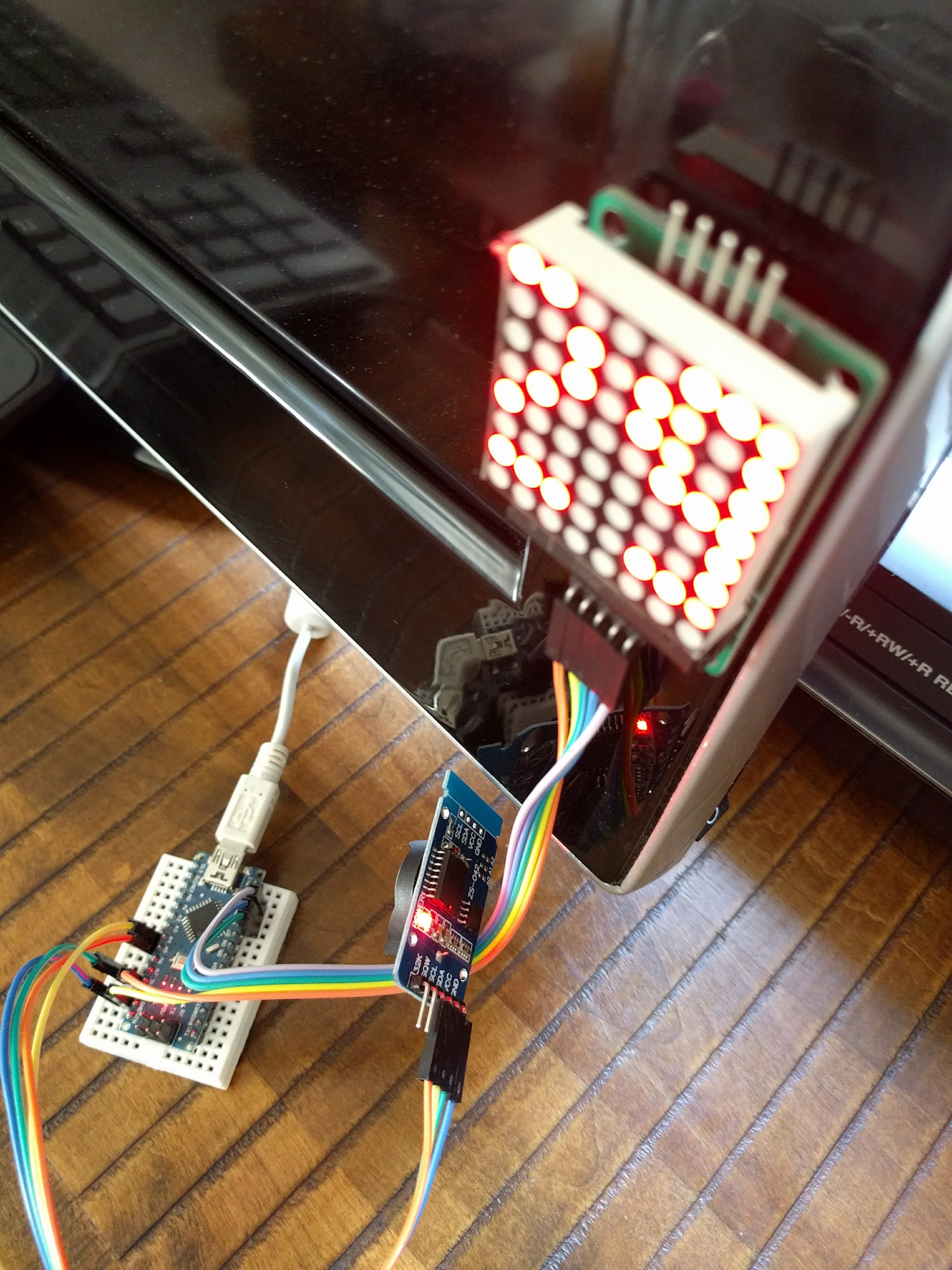
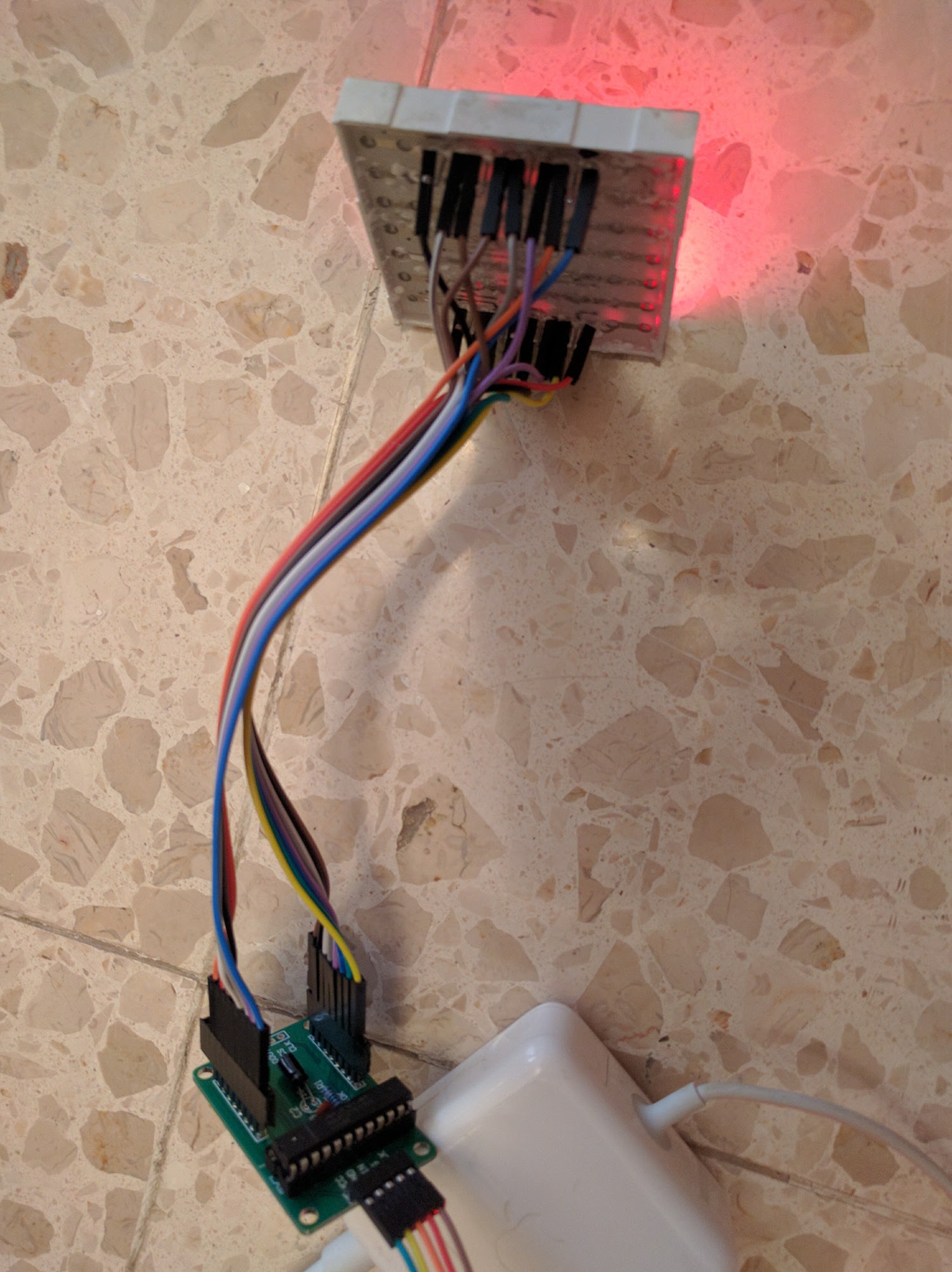
When I plugged it all in, miraculously, after many hours of trial and error, I'd finally worked it out!
This is it working. (The camera exposure doesn't do it justice - the pixels are much brighter and clearer to the native eye.)
What did I learn?
As I've explained many times in my blog posts, I have no formal training in electronics. I potter about until I get things working. In this case I spent hours fiddling and getting things wrong because I didn't understand the importance of pin numbering conventions and orientation. Had I spent my first hour finding that out, I could have saved myself a lot of effort.
Hopefully this post will help someone else faced with the same problem.