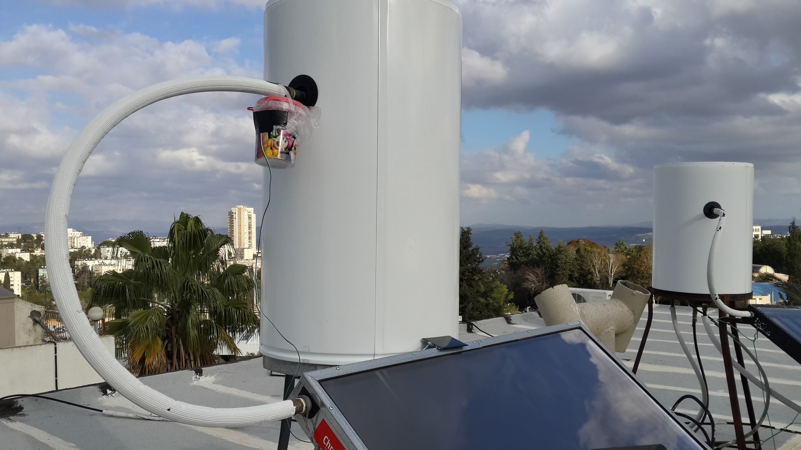
Ever since I've built my Solar charging station I really wanted to do another project involving solar cells, didn't need to build a solar panel again but I very much enjoyed the idea of a project which is powered by green energy. Last month, a friend who enjoyed reading and implementing the water heater project had an idea of measuring the water heater temperature using a thermistor which detects the temperature of the pipes going in/out the water heater and broadcasting it to the web. I was excited about this idea, especially because my water heater is on the roof and it was a good excuse for a project powered by the sun. Long story short, I was working on that project for the last month, with some interesting challenges on the way, hardware and software related. Here's the final outcome on my water heater, it runs on a very small polymer li-ion battery which is charged by a solar panel:
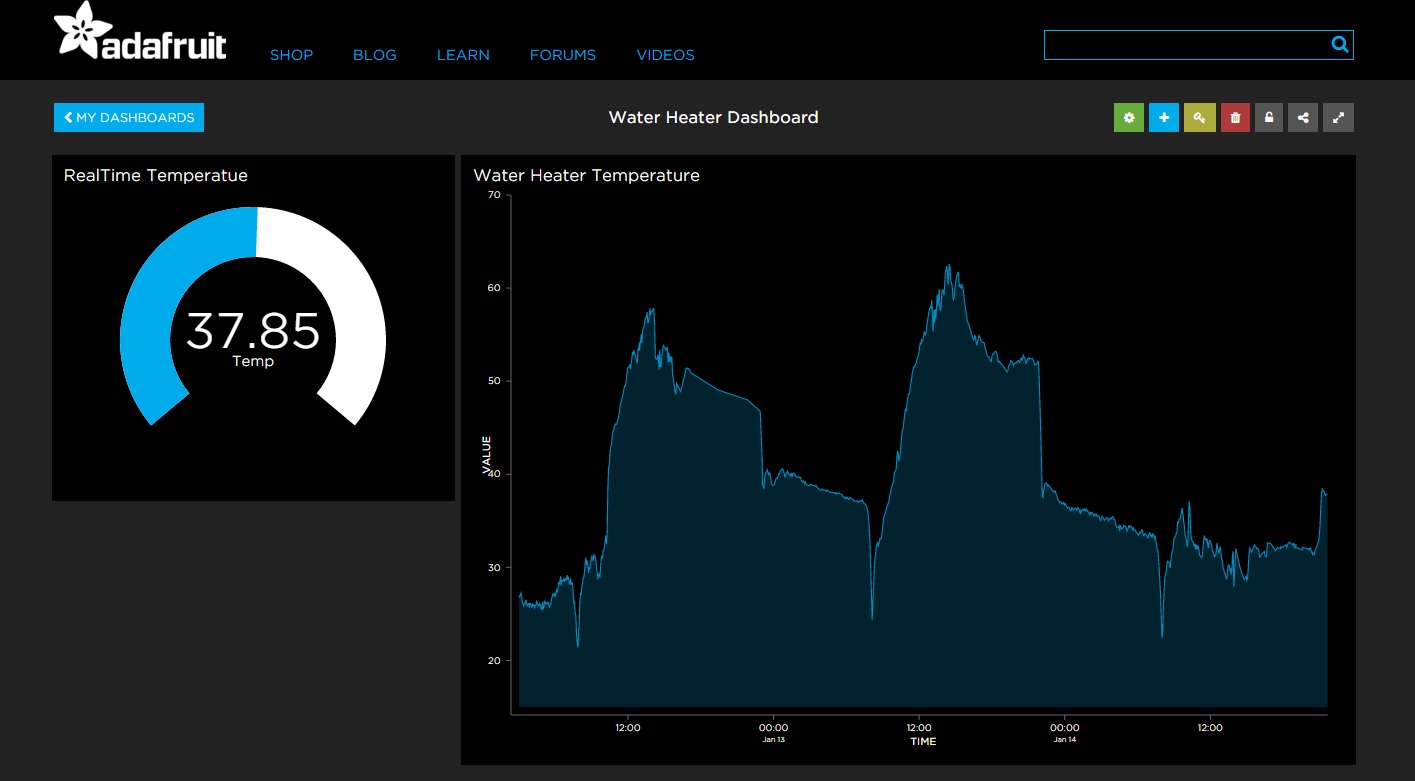
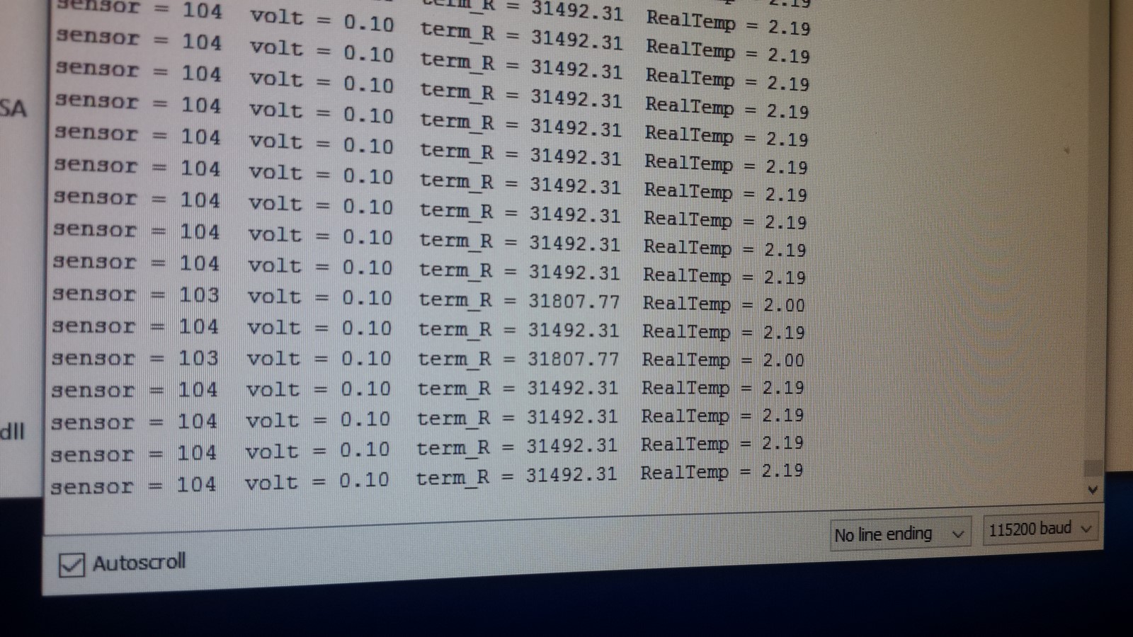
 And here's an example of the data it collects:
In the next sections I'll try to describe the steps I passed on the way. If you belong to the tl;dr community - Hope you enjoyed reading up until here! Here you can find the circuit and code for this project.
Thoughts about Battery-Powered Gadgets
Powering the ESP8266
The ESP8266 micro-controller needs voltage of 3-3.6 volts to work properly, 3.3V is the optimal value, and it is preferred that it will stay stable. If we use normal 2x1.5V AA batteries or 3V coin battery the ESP8266 will work but as the batteries power diminishes the micro-controller will stop working - So the optimal solution is to power the ESP8266 with a battery which supply more than 3.6V, and use a voltage regulator - The question is, how to choose a good voltage regulator?
For a start, I've decided to use polymer li-ion battery, mostly because of its size and charging options (I'll go more into details later on). The polymer li-ion battery can supply around 3.6 to 4.2 volts. If you have read some past posts about my other ESP8266 projects, you have probably noticed I always use the LM1117 voltage regulator to drop 5V or 12V to 3.3V and power the ESP8266. I've tried using this regulator and found out it is not suitable for two reasons:
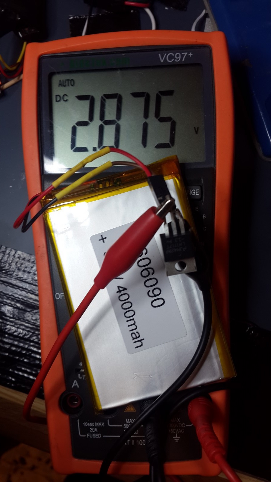
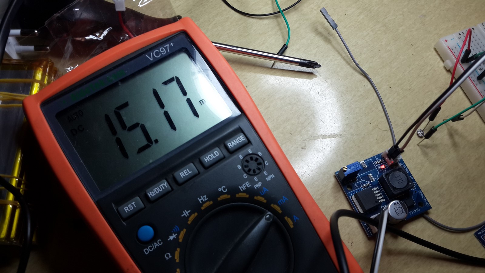
1. It has high drop-down voltage, about 1V. That means that we need a power source which will always supply at least more than 4V. Checking it with li-ion battery, charged to around 3.8-3.9 volts gave this result in the LM1117 output:
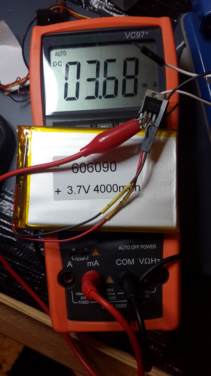
2. The LM1117 draw about 4mA when NOTHING is connected to it ("Open Circuit"). If we plan a low power gadget, we should consider other components which are more low power than the LM1117.
I've tried several other DC-DC components I found around my stuff. They could supply the needed 3.3 voltage but were even more power consuming when testing them in "open circuit".
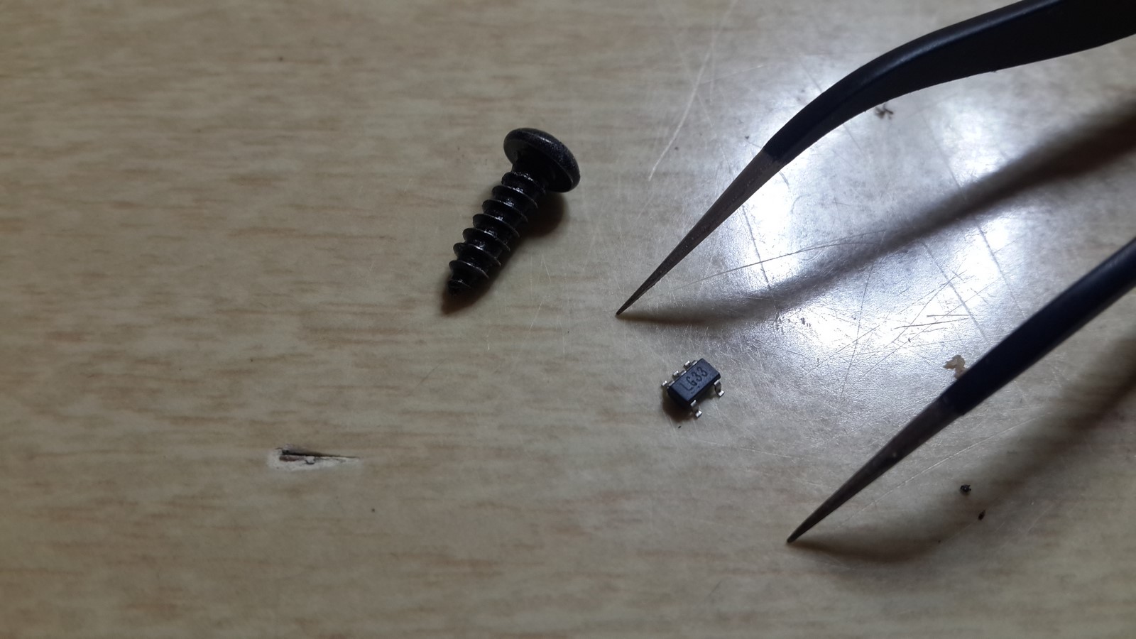
Then, a friend brought me one of his voltage regulators. Its brand is MIC5219 (LG33), and it was the smallest electronic part I ever had to deal with:
It was a bit challenging, but I managed to place it on a SOC to DIP8 board and solder it:
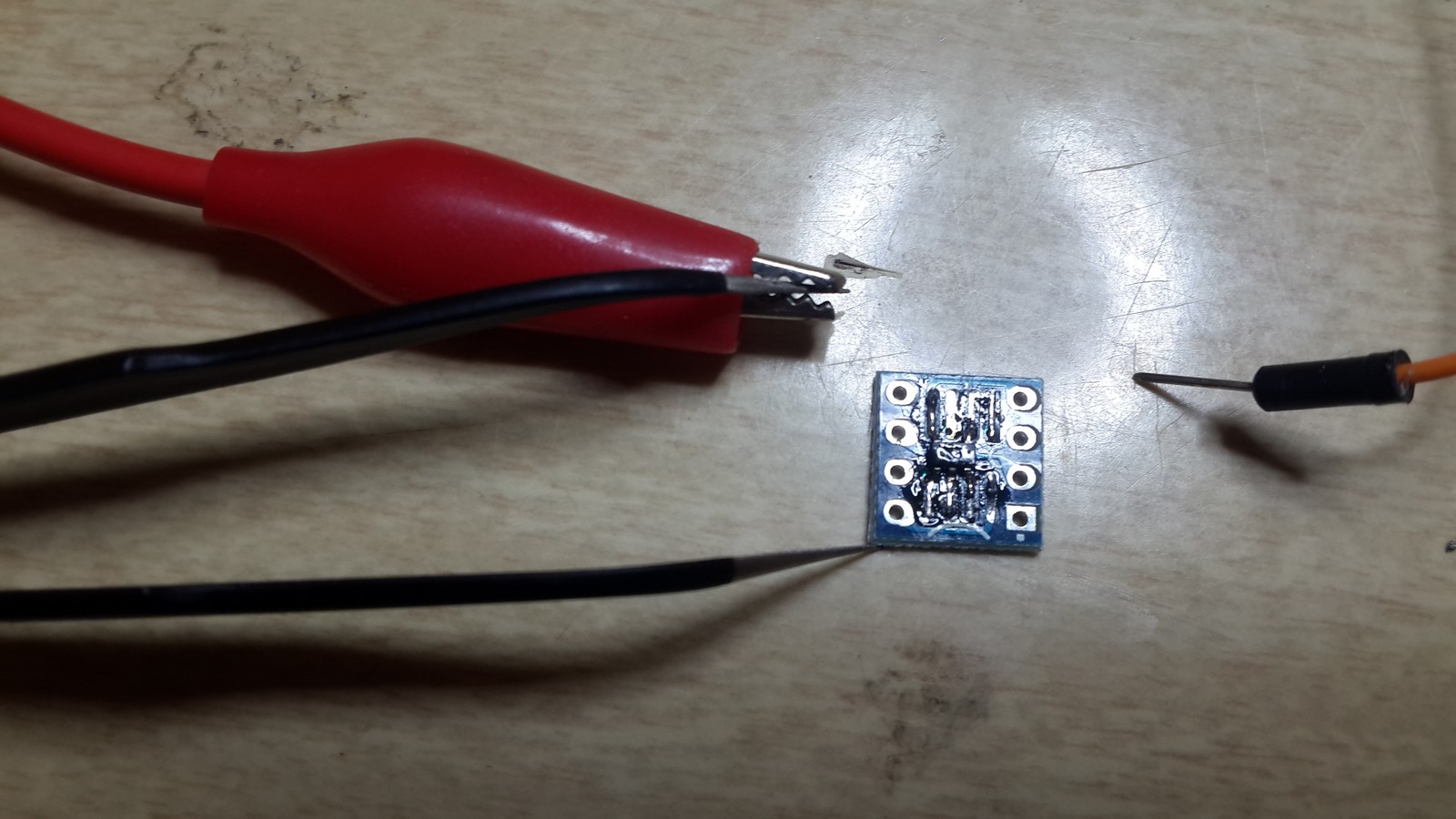
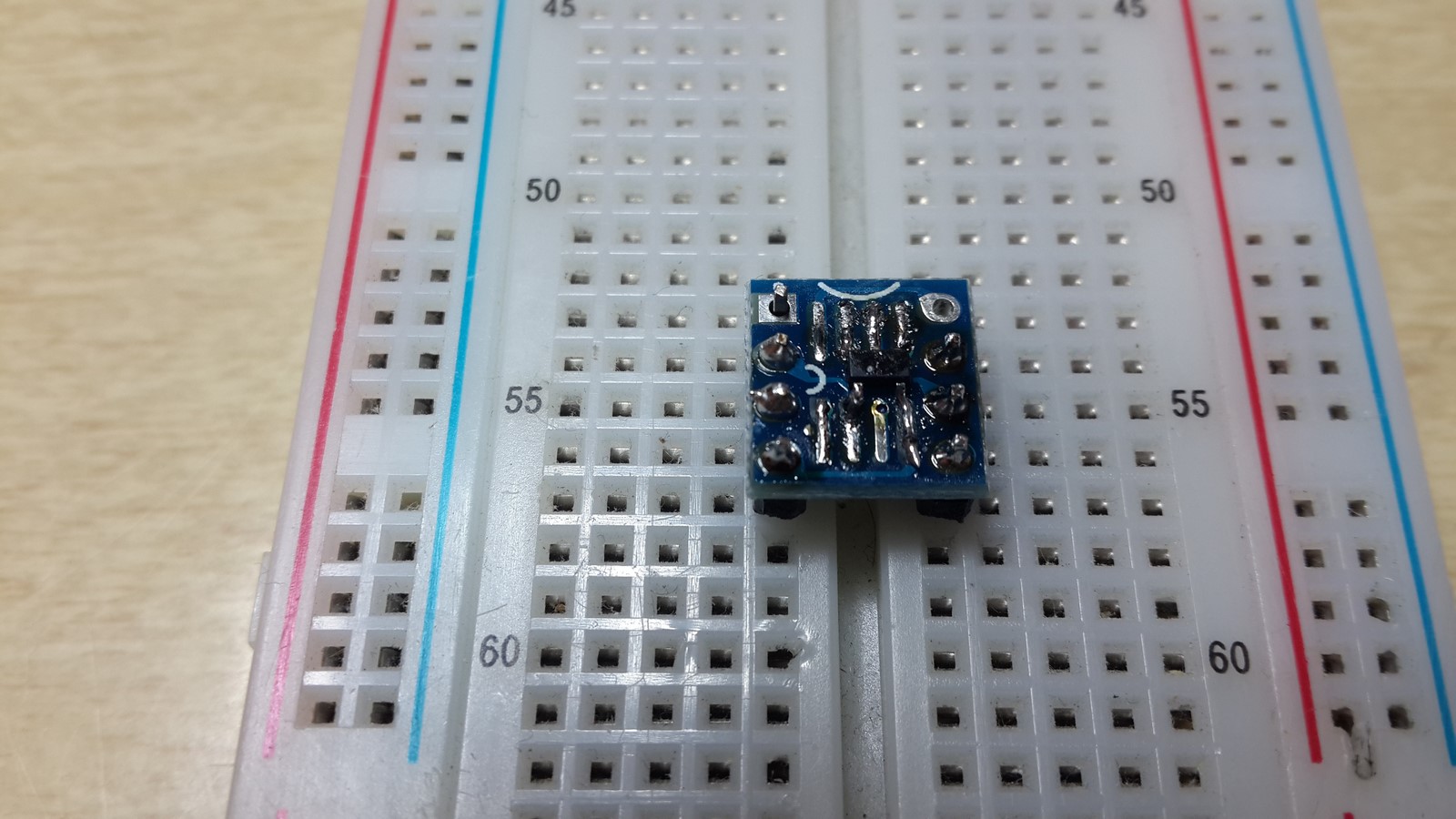
After testing the connections, I could use it on a breadboard and start testing its performance.
According to its datasheet, a circuit needs to be built around it before its first use
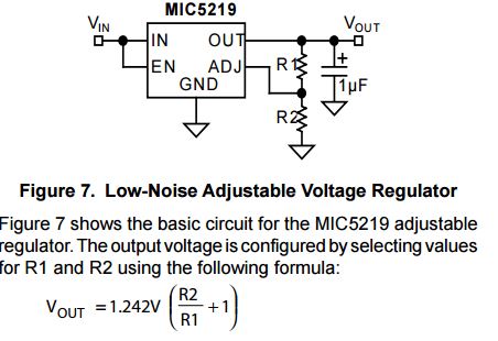
and the resistors are selected such that the equation will give 3.3 volts. I chose 10KOhm and 5.6KOhm which have high enough value so there won't be too much current draw through them. Now lets go to the testing part.
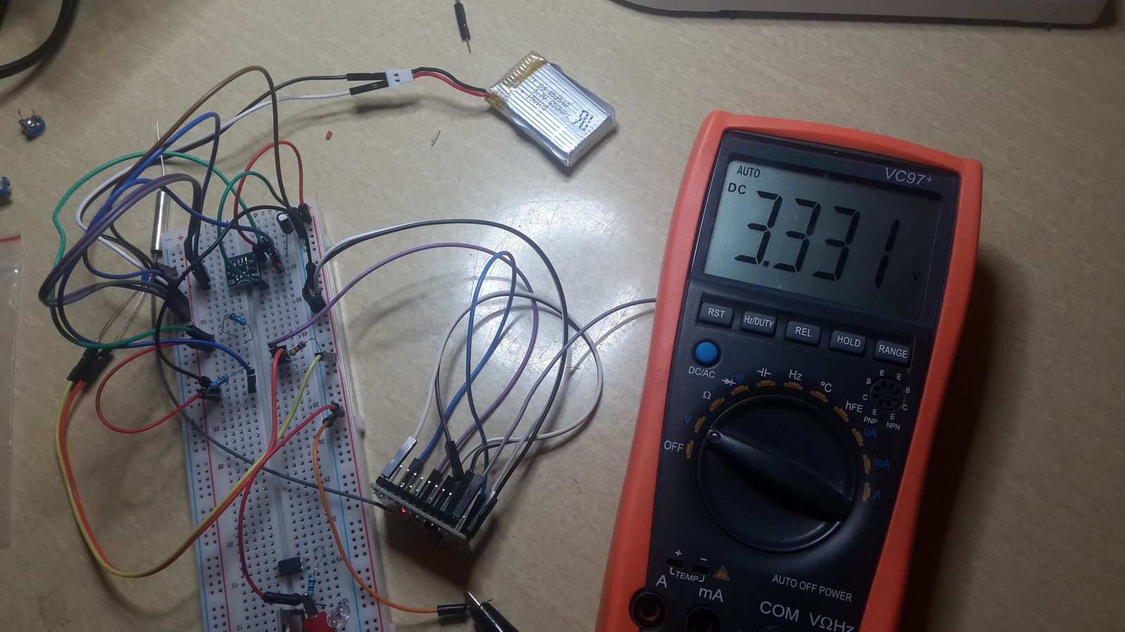
- Voltage - Good! 3.3V
- Open circuit current - Good! Only 117 micro-amperes (0.117mA)
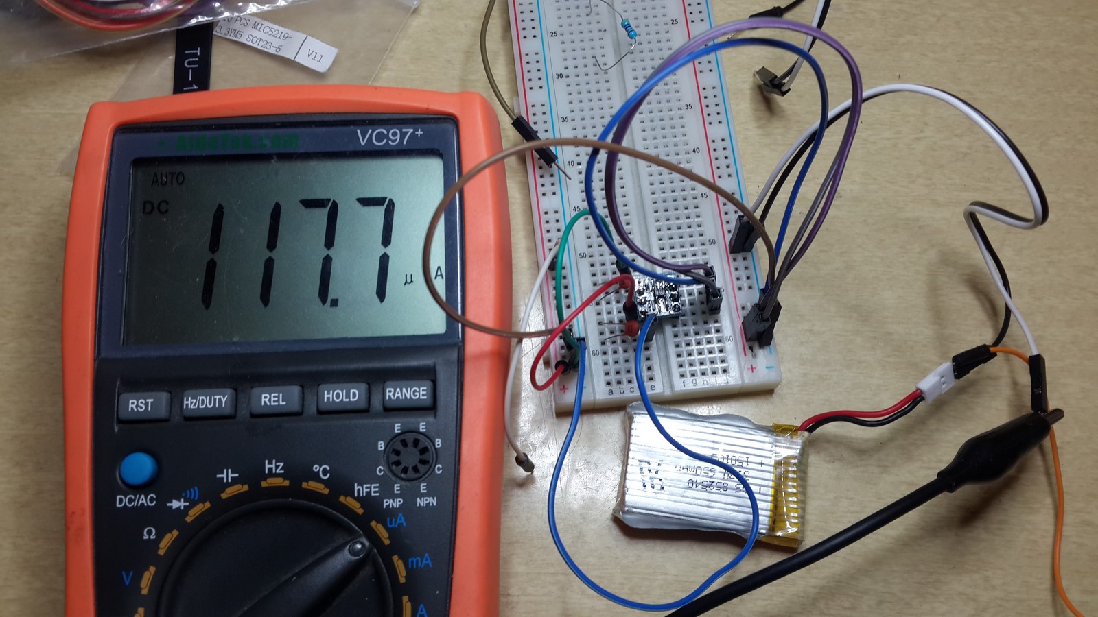
We are good to go then! We have a low-power circuit to power the ESP8266.
Sleep Mode: Reducing Power
The next step in designing a low-power gadget is to use the micro-controller as little as possible. In this project , for instance, we would like to get the water heater temperature, but it is not so important if this is the temperature we measured a few minutes ago - It'll most likely be very similar. I decided to send myself the temperature readings every three minutes - But what should the ESP8266 do during these three minutes? Go to sleep...
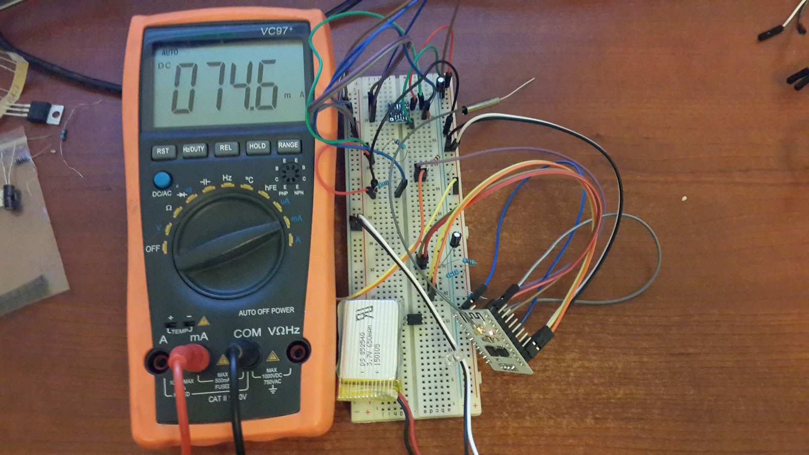
The ESP8266 is a relatively high power consumer in comparison to other micro-controllers. It draws around 70mA-120mA when it is on, with peaks of 250mA due to the WiFi transmission. Assuming I use 650mAH battery, it'll drain it after around six hours (You can read in this post more about batteries). The idea is to send the temperature values to the web and then shut down for a three minutes. The ESP8266, as most of micro-controllers, has this functionality so it can shut down all its modules except a timer and a comparator. When the timer value is equal to the comparator value it changes GPIO16 from HIGH to LOW. If we connect GPIO16 to the RESET pin, the execution will reset the ESP8266 and it'll start the process all over again - sending the values and go to sleep for another three minutes. How much power it saves us? Let's check! When the ESP8266 is on I've measured around 75mA-100mA
When the ESP8266 is in sleep mode:
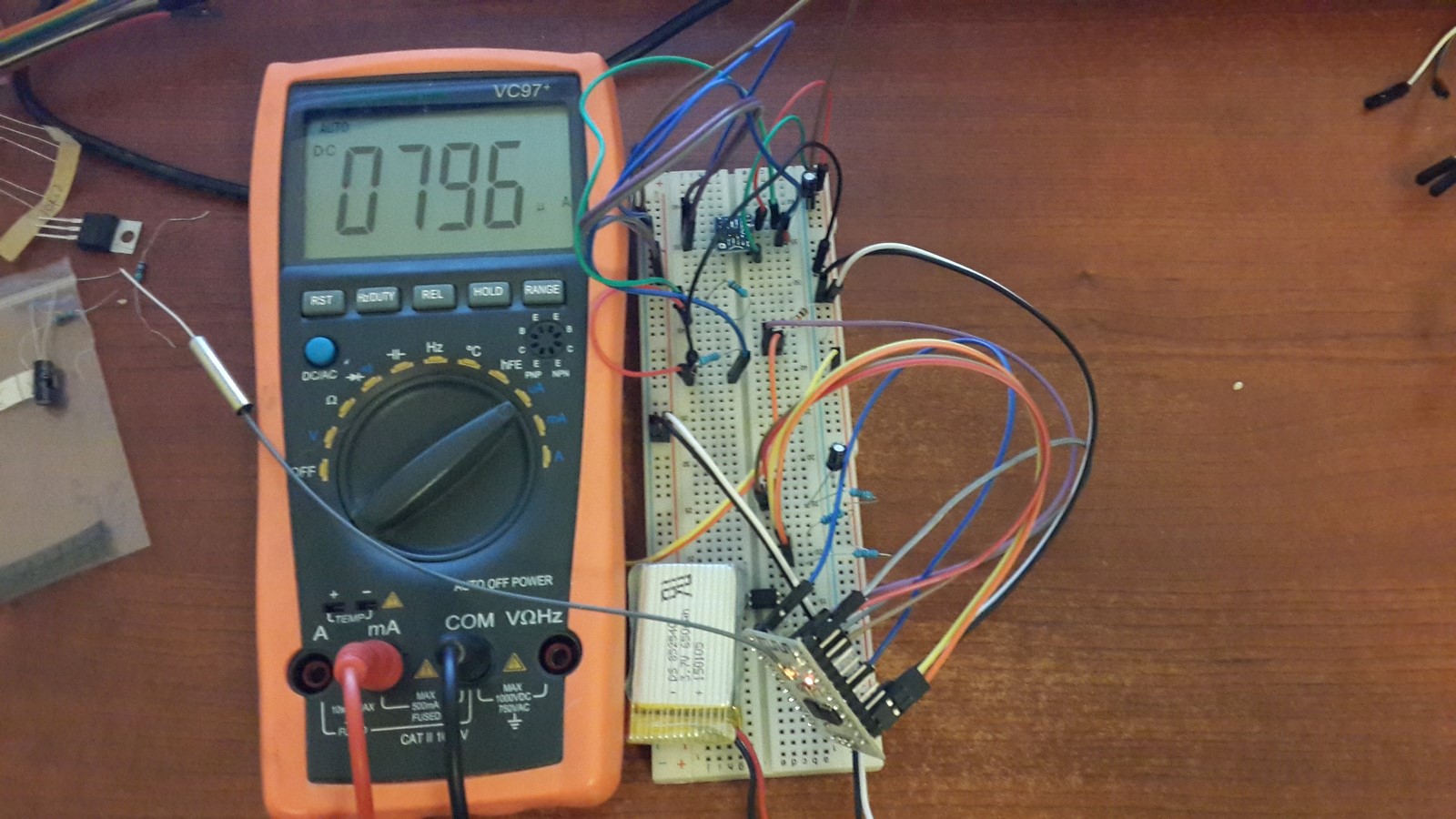
A bit less than 800 micro-ampere (0.8A). In fact, it's even much less. As we've seen earlier the voltage regulator takes about 120 micro-ampere, and the red led on the ESP8266 takes about 600-650 micro-ampere - Which leaves us with a power consumption by the ESP8266 of less than 80 micro-ampere. The red led can be easily soldered out when the project is done and everything works, and so we left with "near-zero" power consumption. Calculating the numbers, assuming roughly the ESP8266 is on for half a minute drawing 100mA and then sleeping for three minutes with near-zero consumption, meaning the average current drawing is around 15mA. That means that the 650mAH battery can power the device for more than 40 hours before it will need to be charged! Cool ha? (if you're a geek of course...)
Charging the Battery
OK, so we understand that the battery can last for 40 hours, which is almost two days, but we want it to work for weeks/months/years. My solution was solar charging. I ordered from Ali Express this solar panel, 5V and 250mA max, and also this li-ion charger, which also suits for one-cell polymer li-ion batteries . As I explained in this post, charging li-ion batteries is more complicated than charging other batteries, so a charge controller must be used. This type of charge controller can be powered by 5V, so it suits perfectly to the output of the solar panel and it charges a 4.2 volts li-ion battery (or polymer li-ion). The circuit cannot be powered only with the solar panel since the output of the charge controller must have a voltage of less than 4.2V so it'll start pushing current towards the circuit. Using this specific solar panel and battery means, that if there's a direct sun and the panel does produces current of 250mA, it'll charge the battery in about 2.5 hours. Even if it is a cloudy day and the panel produces only 100mA, it'll still take around 7 hours for full charge of the battery. Where I live it is mostly sunny, and in the shortest day in the year there are still around 10 hours of light. Adding the fact that the battery can last almost two days making it pretty obvious that this tiny solar panel will be enough for this project. I'll show some current draw testing later on in this post.
Thermistor: What Is It and How to Use It?
Quoting Wikipedia:
A thermistor is a type of resistor whose resistance is dependent on temperature, more so than in standard resistors.
Which means that a thermistor is actually a resistor, and it's resistance changes with temperature rises/drops. If we know the relations between the resistance and temperature we can measure the temperature using a micro-controller.
The ESP8266 micro-controller has a single analog input, where a voltage between 0-1 volts can be measures and be interpreted to bits represent by integers of range 0-1023. In order to calculate the thermistor resistance, we will use the next simple circuit, a voltage divider:
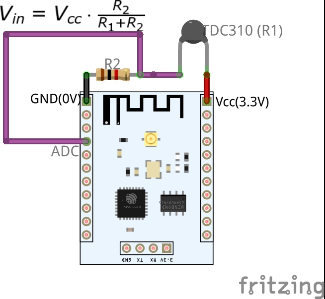 Where the voltage going into the analog input can be calculated as:
$$
V_{in} = V_{cc} \cdot \frac{R_2}{R_1 + R_2}
$$
Which means that by reading the analog input we can calculate the thermistor resistance value:
$$
R_{th} = R_2\cdot(\frac{V_{cc}}{V_{in}} - 1)
$$
The relations between the temperature and the resistance are a bit more complicated:
$$
T = \frac{1}{a + b\cdot\ln(R_{th}) + c\cdot\left(\ln(R_{th})\right)^3}
$$
Where a,b,c are pre-defined values which can usually be found on the thermistor datasheet.
The reason I wrote all these equations is to clarify an important issue I understood while playing with this sensor: As seen in the last equation, the relations between the voltage measured by the ESP8266 and the temperature is not linear. That means that we cannot expect, that for every $\Delta V$ we will get the same $\Delta T$. For example, assuming $R_2$ is 1KOhm - If I get reading on the ADC of 100 (out of 1023), the calculated temperature is around $ 3^oC $, and a value of 200 will give $ 15^oC $. On the other hand, value of 900 is $ 55^oC $ and 1000 is $ 58^oC $. So a change of 100 (~100mV) at low voltage results 12 degrees difference and at higher voltage is 3 degrees difference - Hence, the resolution in high temperatures will be much better than in low temperatures and also more stable (Think about small measurements errors). I chose $R_2$ to be 1KOhm so I will have good resolution around my working area (water heaters usually go up to 60 Celsius degrees). I didn't solve this issue because the precise temperature was not so important to me - But if it is important to you, a good solution is to use a MUX with several resistors, and for each range of temperatures switch to the resistor which will give the best resolution for this range.
In my project I've used the TDC310 5mm thermistor. I started by calculating the equation from R to T using the parameters the datasheet defines. Then I looked at the graph presented in the datasheet:
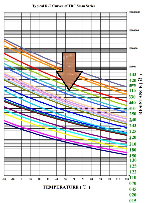 and compared it with the equation. I've noticed that the equation is pretty accurate around 20-30 degrees but less accurate for higher temperatures. This fact eventually made me not using the T(R) equation. Instead, I took the data of every five degrees from the graph and made a look-up table, predefined in the code, where in oredr to calculate the right value I assume there are linear lines between these points.
Another point that should be taken into consideration, is to understand the practical errors we can get in the first and second equations I wrote. Since we going to use a battery, the Vcc voltage will not always be exactly 3.3V, and due to the long cables which we expect to connect the thermistor, it's calculated resistance will not be exactly its true resistance. So the corrected first equation should be:
$$
V_{in} = \left ( V_{cc} + \Delta V \right ) \cdot \frac{R_2}{R_1 + \Delta R + R_2}
$$
Leading to the corrected second equation:
$$
R_{th} = R_2\cdot(\frac{V_{cc} + \Delta V}{V_{in}} - 1) - \Delta R
$$
Using thick cables and good soldering, we can get very small values of those added values making this correction negligible.
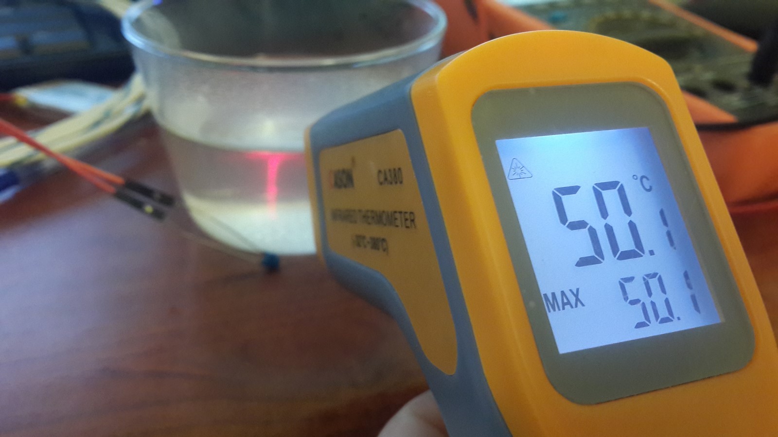
For the testing part, I've used a thermometer gun to test different objects. For low temperatures I've used a bag of ice (The thermistor is not straight inside the ice so the temperature will stay above zero). Here's the gun:
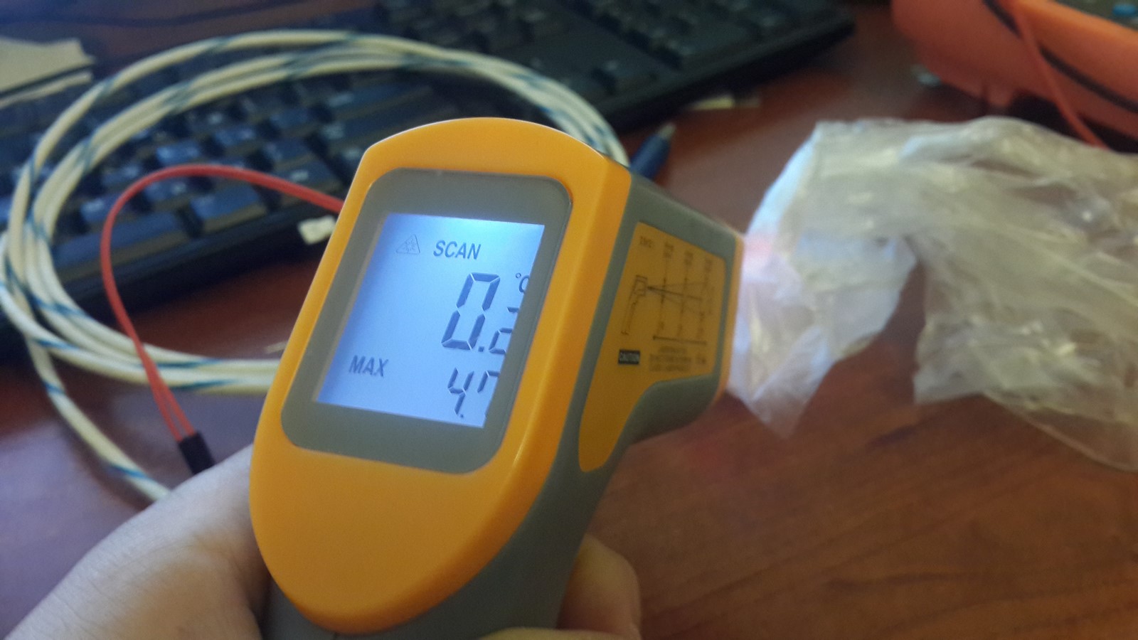
and here are my calculations:
Then I switched to a glass with hot water. Here's the gun:
and my calculations:
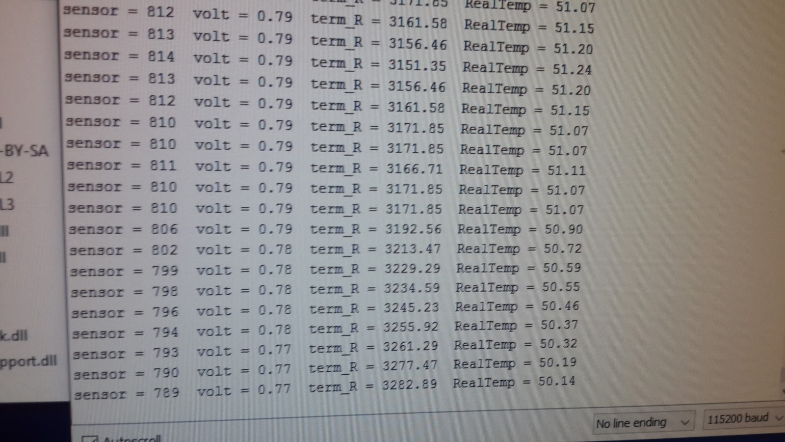
Also, for a bonus here's a movie of measuring the hot water glass and removing the thermistor afterwards, notice the changes in volts,resistance and temperature.
Software
After explaining about all the hardware issues, and before describing the setting up of the entire system, I'll shortly describe the software, which is not too complicated.
My code can be found here.
As described before, the software calculates the temperature, sends it to the web via WiFi, and then goes to sleep for three minutes. When I wrote the first version of this code, I wrote it such it sends the data to my server via html requests and on the server side a webpage which saves the data and writes the temperature. It wasn't very nicely presented but it seems to work good and fast. Then, while I was affected by Notamacuser attempts to log and present his data, I remembered that a while ago I've signed up to Adafruit IO Beta website, a cozy platform to activate and receive data to and from IOT devices. I set it up pretty quickly, downloaded their library for Arduino/ESP8266 use and used their example for sending data using REST API. The way it works is such that each user has a unique key and can create different "feeds". Using the key and a certain feed and value you can simply upload your data to their website, then visualize it on a graph. The work with Adafruit IO has its pros and cons, which I'll describe more later in the "testing" section, but eventually it's a BETA which means it will get better with time.
Back to the code, here are some notes regarding it:
- When using the .h file, you must first change these lines to your parameters:
#define SSID_ME "YourSSID"
#define PW_ME "YourPW"
#define AIO_KEY    "ADAFRUIT KEY"
#define FEED_NAME "ADAFRUIT FEED"
- Later on in the .h file, if you are using a different thermistor than mine, you can change the look-up table for the relations between resistance and temperature.
int T_LUT[14] = {0, 5, 10, 15, 20, 25, 30, 35, 40, 45, 50, 55, 60, 65 };
long R_LUT[14] = {35000, 27000, 20000, 15000, 12000, 10000, 8000, 6000, 5000, 4000, 3300, 2700, 2200, 1900};
If you just need to slightly correct the temperature you can just change the value in "#define DEGREES_CORRECTION".
On the .Ino file: It start with
setup(), where we setup the WiFI and Adafruit IO class.On the main loop we:
- Check that the WiFi is connected.
- Get the temperature from the analog input.
- Try uploading the temperature value to Adafruit IO.
- If the upload worked, send a sleep command for 180*1000*1000 micro-seconds, or three minutes.
If the WiFi is disconnected or we didn't succeed uploading the data, we will repeat the process four times and then, succeeded or not, go to sleep for three minutes.
In the
getTempFromAnalogValuefunction, The calculations I use are as described in the thermistor section, with using the look-up table and theDEGREES_CORRECTIONfor the final result:
  double voltVal = ((double)AnaVal / 1024.0) * ADC_MAX_VAL;
  double thermVal = (VCC / voltVal - 1) * SEC_R;
  Temp = DEGREES_CORRECTION + (((double)thermVal - R2) / (R1 - R2) ) * ( T1 - T2 ) + T2;
I left as a comment the real equation which suppose to give the temperature from resistance (As I explained before, it wasn't accurate enough in high temperatures).
Putting All Together
As always, this is the fun part with more photos than words.
Circuit
Here's a sketch of how the final circuit should look like:
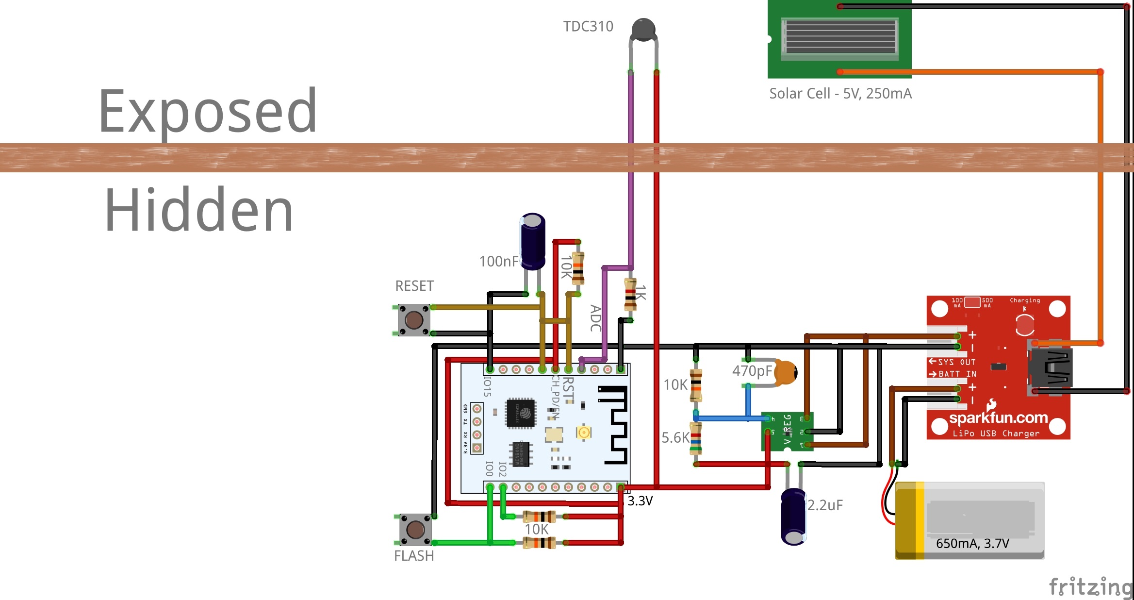
A few notes about the circuit, some of them I found from this interesting post:
- The voltage regulator and the thermistor are connected as explained in the previous sections.
- The reset pin is connected to GPIO16 as explained before, but also pulled up to Vcc and connected through a capacitor to Ground. I advise using these connections every time you plan to connect something to the reset pin since it'll keep it from going low (and then reset the ESP8266) just from some small electrical noises.
- GPIO0 and GPIO2 are pulled up to Vcc. These pins define the boot option after reset and as the ESP8266 going to be booted a lot, we don't want it to mistakenly boot in flash mode - Only one mistake is enough and the entire gadget is useless until we reset it manually.
- Flash and Reset buttons are also good for convenience, but not obligatory of course :)
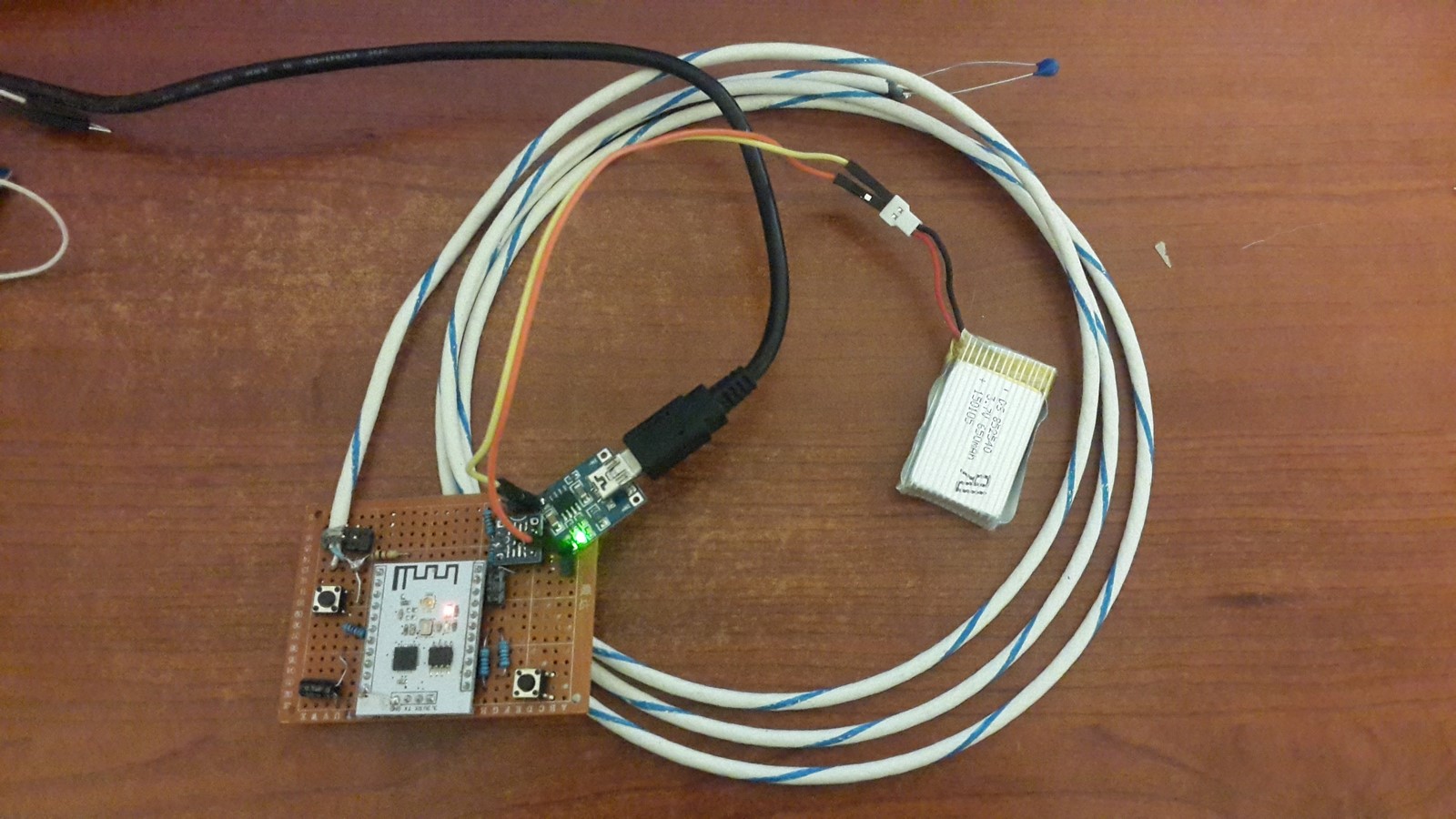
After a few hours, the circuit was ready for first use:
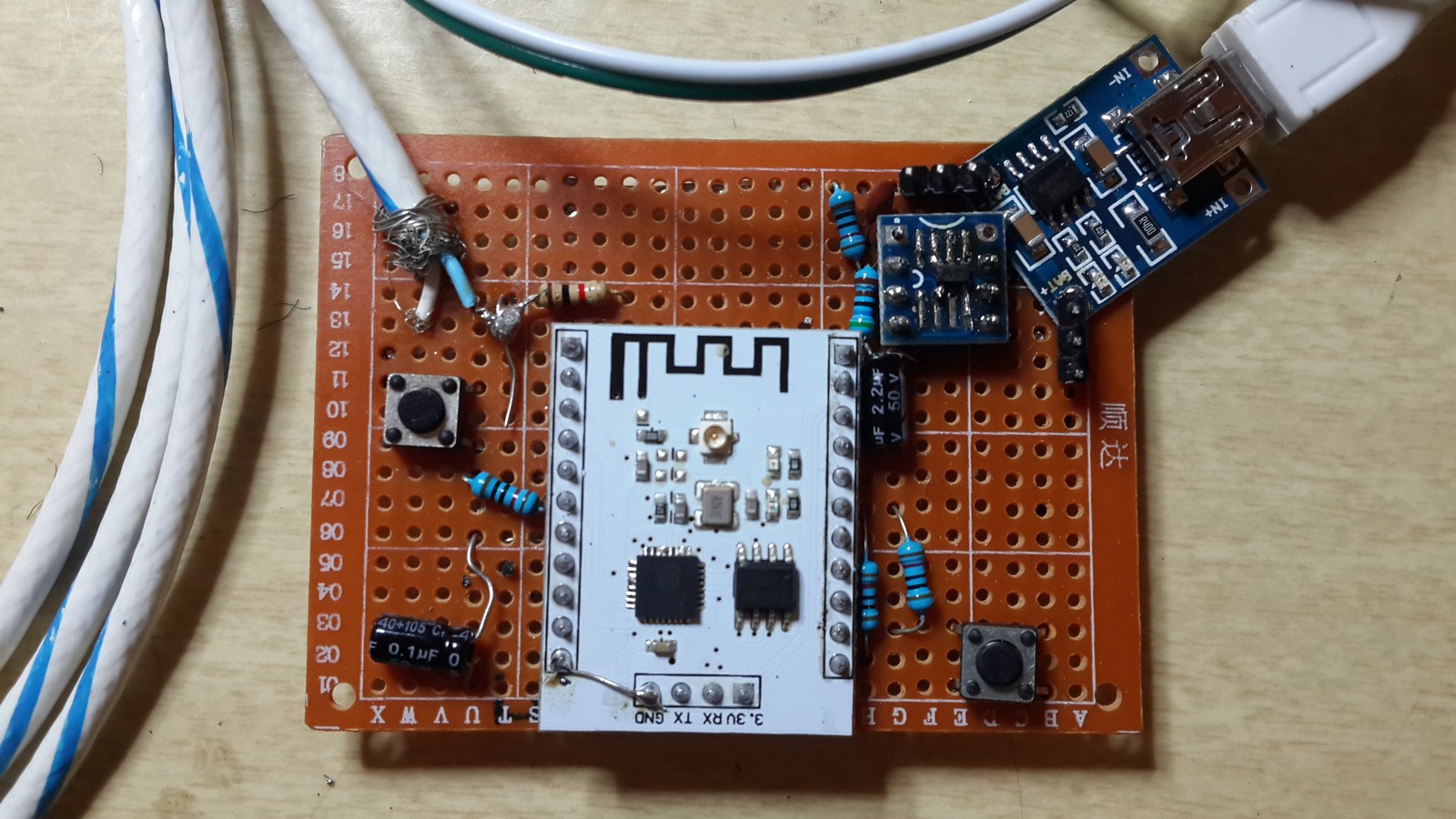 With long cables (with low resistance) for the thermistor and the solar panel.
Oops!!! While soldering the thermistor I accidentally destroyed it using too much force when holding it.
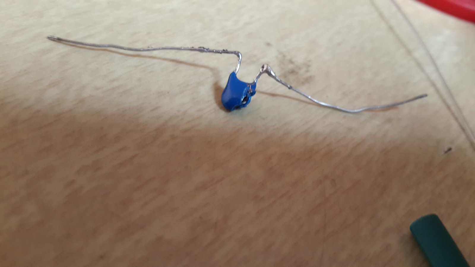
I didn't have another thermistor so that was the low point of this project, when I thought everything going to be on hold until I get a new one. Then I remembered two weeks before I had a problem with my AC. The technician came and switched the AC electronic card, and during the process, we talked a bit about my projects. At the end he left me the bad card, saying I should keep it and use its parts. It was just laying there, in my junk pile and then it hit me that the card has a thermistor connected to it!
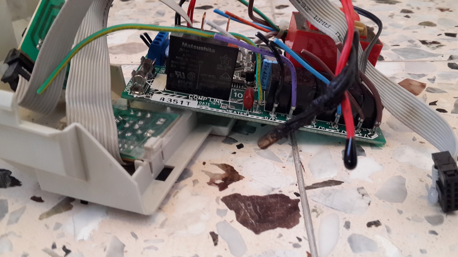
It was already covered with epoxy, so no need to set it up for a rainy day. It wasn't the same brand as the old thermistor of course and I didn't know what brand is it because of the epoxy. So I made some tests and realized that a small correction of four Celsius degrees will give me very similar results to the last thermistor.
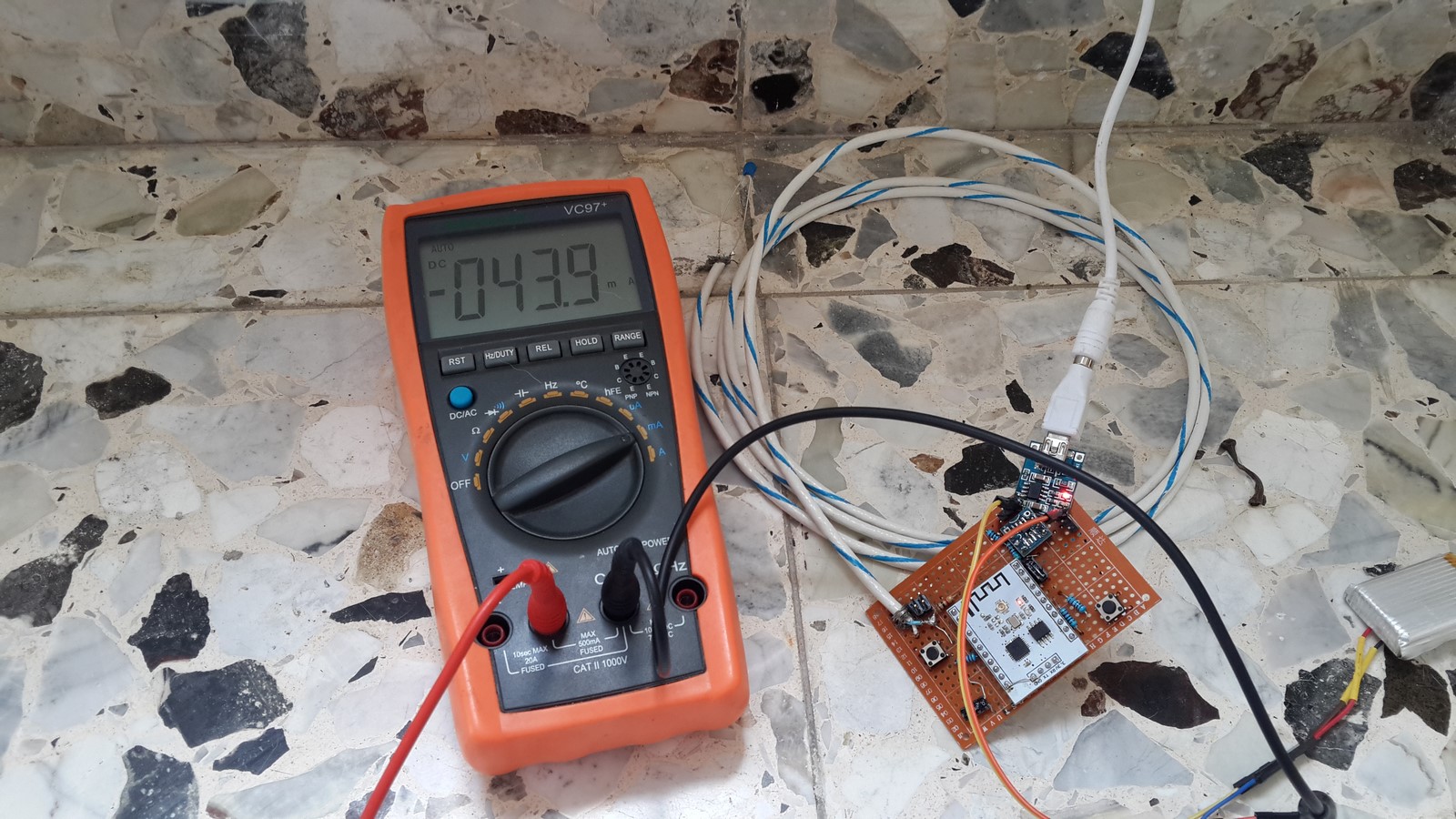
The circuit was ready and I had to test it before setting up the device. It was mostly sunny outside, so I put the solar panel outside my window and start measuring current.
When the ESP8266 was working, I measured -40mA, which means the battery is being charged even when it's powering the ESP8266.
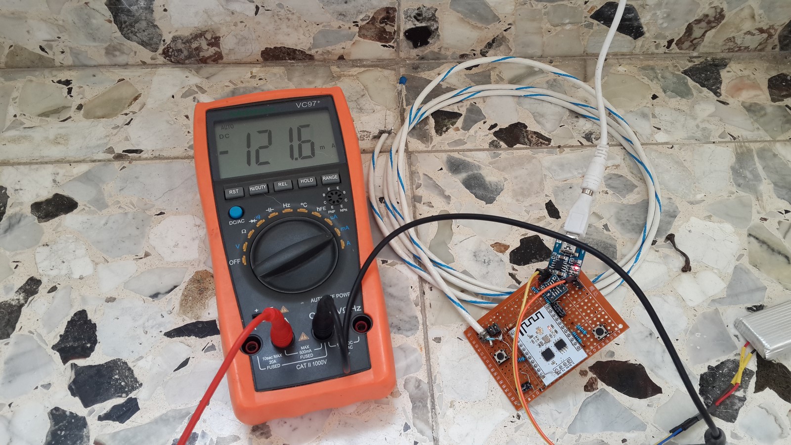
 When the ESP8266 was in sleep mode, the charging was even faster - went up to -120mA
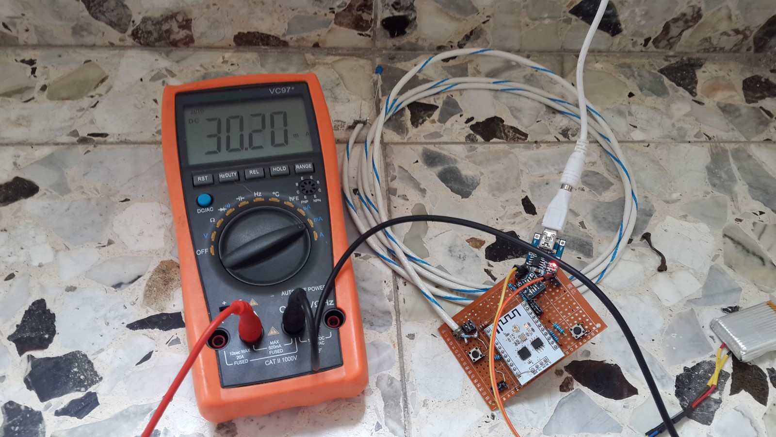
 After a while it became cloudy and I tested it again, when the ESP8266 was working, the current was around 30mA, which means the battery is not being charged but still supply less power than expected.
Setting Up
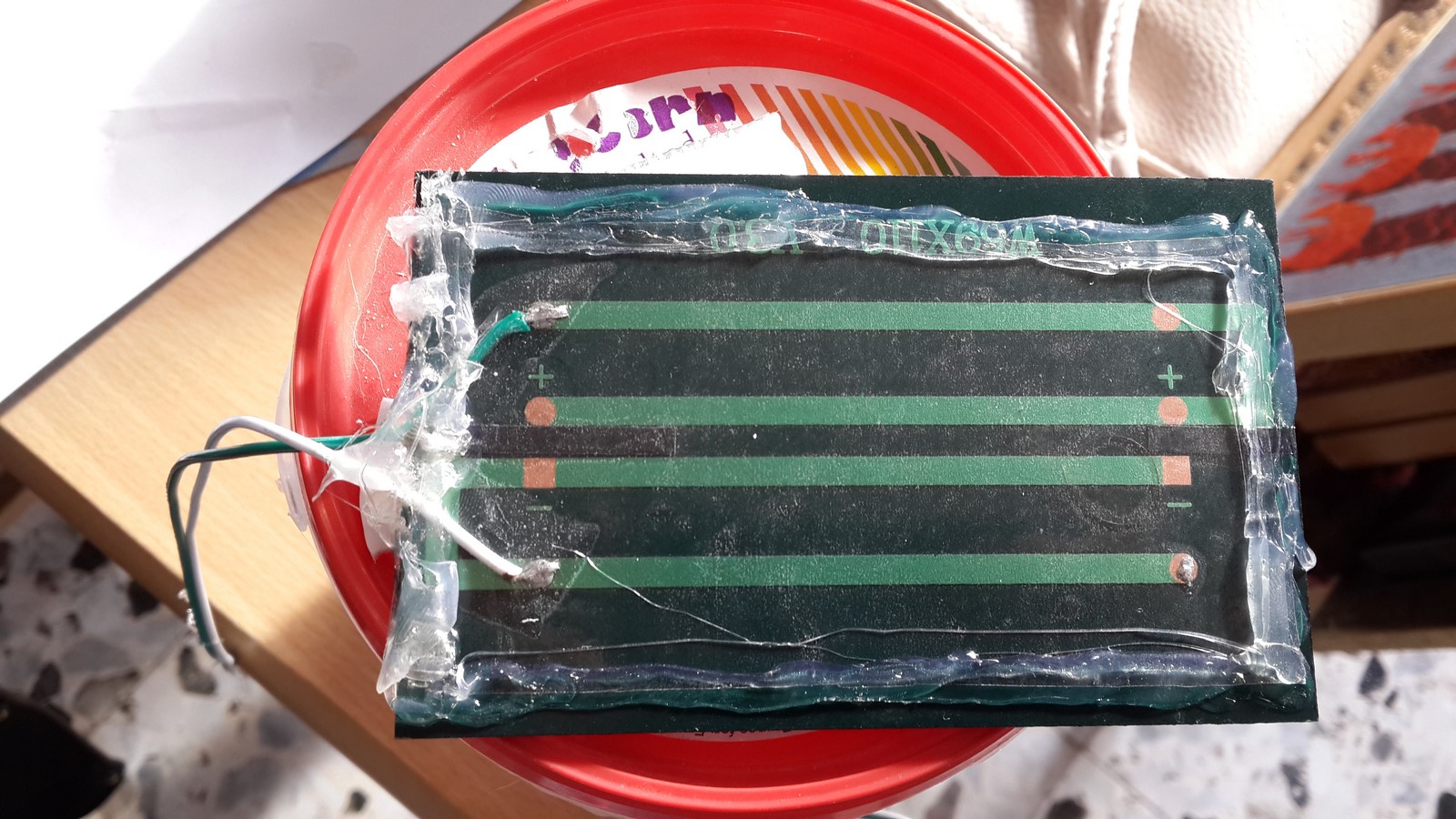
The next step was setting up the device on the roof. The main idea was to create a good packaging for everything which can be ruined by rain, which is mostly all parts except the solar panel front and the thermistor. I've started by covering the back of the solar panel with duct tape wrapping (Not sure what the right name), and then cover it around with hot glue.
Then, I took a plastic box I had (from Disneyland Paris :D), made a small hole next to its top, put through the wires of the thermistor and the solar panel, and then sealed it also with a lot of hot glue.
Next, I put the board inside the box
closed the box and covered it with some plastic bags
Then, I hung the box next to the pipe which connects the heating plates on the roof (the plates heating the water by the sun) and the water heater "hot water" area.
and last, setting up the solar panel in a place where it will get a lot of sun
Note: The thermistor must be attached to the tube and isolate from the surroundings as much as possible to avoid the effect of the environments temperature. I've taped it with a lot of gaffer-tape and eventually covered it with some carton plates.
Testing
And now we play the waiting game. I had to wait patiently to get some data that I can actually analyze. Up until now, the device has been working for several days. The device works flawlessly but it seems that using Adafruit IO web-server wasn't such a good idea, at least not while they are still on their BETA. Their website crushed several times since the ESP8266 had started sending data. At first I thought there was something wrong with my device because I could see the graph but it didn't get new data, then the entire server crushed and it was obvious what have happened. Also, sending data to their servers takes about 20 seconds which means the ESP8266 works about 30 seconds before it go to sleep mode. That's three times the time it took to send data to my own web server. But still, their code and web site were very intuitive and I believe they will improve their servers with time. So for a final photo lets check the temperatures from the last three days and do some analysis:
- The beginning of a sunny day - Water are getting hot by the sun.
- Evening - Taking a shower and finishing the hot water.
- 8am - Using hot water in the morning making very cold water from the night to run in the pipes.
- Another sunny day - same as #1.
- Another shower - same as #2.
- 8am in the next morning - same as #3
- A cloudy day - water doesn't heat.
- An hour ago - I turned on the electric water heater.
That's it - I wonder how long this device will last. Perhaps I'll ran out of patience and take it out for an upgrade in time. Any suggestions or comments? please feel free to comment below.
AA