How to accurately control the timing and motors of a stepper motor. A practical example on an unusual project.
A watch winder is typically a small box with a motor that is powered by a battery. If you wear your Rolex or mechanical watch daily, it is likely that you do not need a watch winder. However, if you wear your mechanical watch less frequently - maybe only while on a mission - a winder is a good idea.
If you have a Rolex Submariner Ref. 6538, James Bond's first Rolex, pictured above, you probably know about the need for watch winder.
One solution is this beautiful craftsman's built, stained hardwood, gold trimmed Allurez Dual Watch Winder:
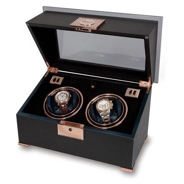 Its just under $2800.
Our solution is to 3D Print our own watch winder. We were inspired by the 3D mechanical design from Bruno Esgulian from his blog.
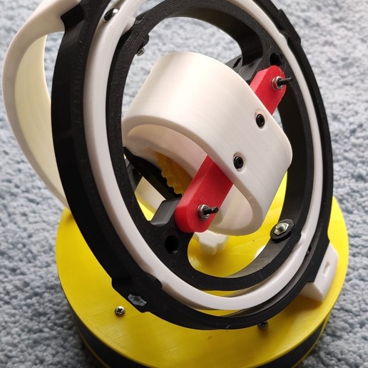
My co-blogger Mike and I recently constructed this 3D design and Arduino-controlled watch winder. Thank you Bruno Esgulian for a brilliant mechanic design. We started with his Arduino firmware, however I rewrote the firmware for Mike's specific requirements.
Hardware Design
We will use an Arduino Nano, as a controller, a stepper motor, a motor controller board, and a 5V external power supply.
The hardware design looks like this -- drawing credit: Bruno Esgulian:
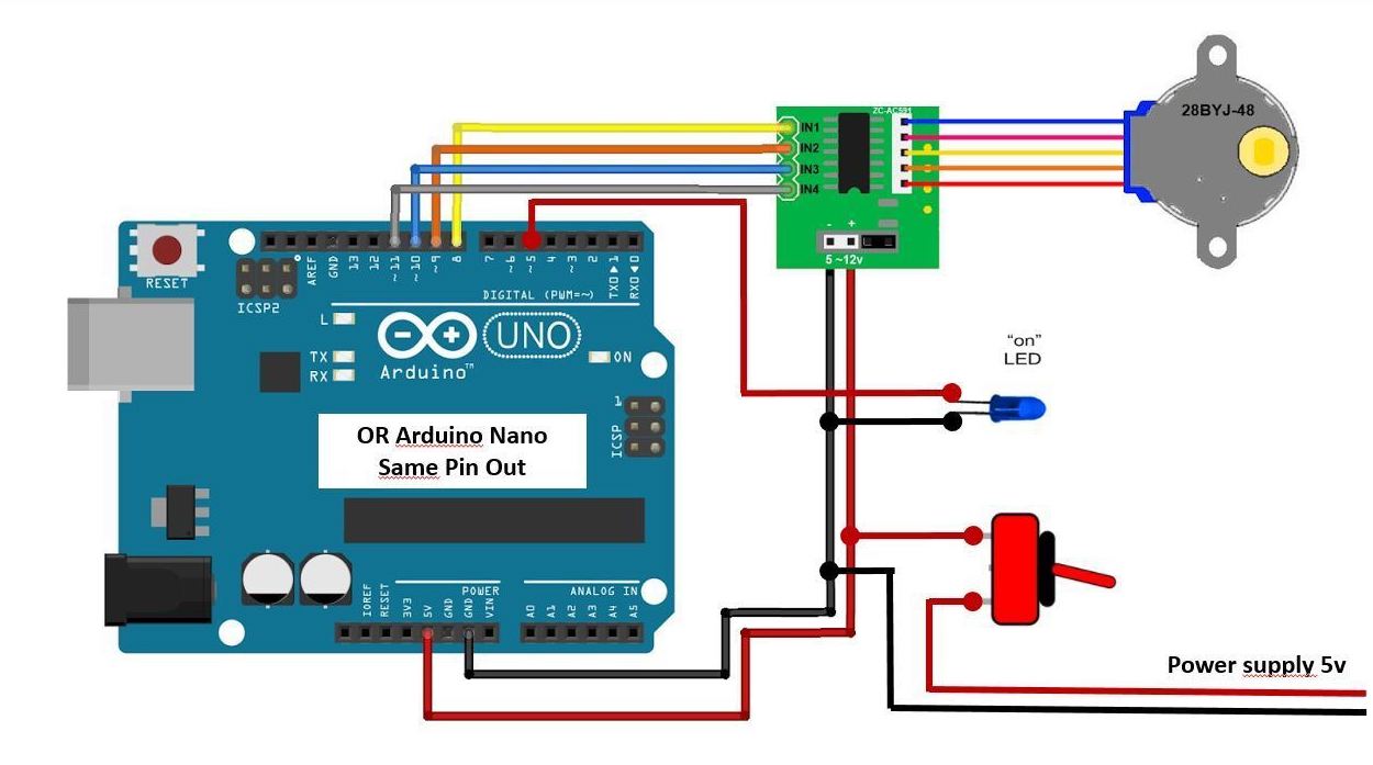
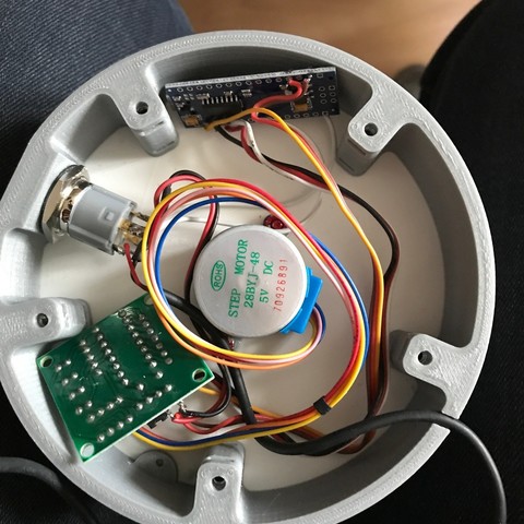
The motor choosen is the 28BYJ-48 stepper motor. The motor controller board a ULN2003 based board.
The connecting signals are hand-soldered, and the components are stuffed into the cavity in the base.
Firmware Requirements
One firmware requirement is to not run it all day and all night. Run it for 1 hour on, and 3 hours off.
In addition we want to turn its stepper motor off when it's not running, to cool the electronics and stepper down and to save energy.
And of course, we want to write very neat and tidy code.
Firmware Design
The design is very simple. We will extend the Stepper Motor library, to have functions which enable or disable the GPIO pins controlling the motor. Other than those extensions, we will use the standard Arduino Stepper Library.
We will introduce the concept of a time-driven loop, described in the next section.
We will have some diagnostics print to the Arduino console - which will be used in the development phase.
How to code a time-driven loop
We want to have a standard way to code an elapsed-time based loop. First, the major time concept in Arduino C is the millis() function, which returns a 64-bit unsigned long number of milliseconds since the Arduino was booted.
Let's declare a typedef or custom type for variables of this type, that is which hold a number of milliseconds:
typedef unsigned long clock_t;
The pseudo-code prototype for some timed operation is,
t0 = millis()
{
    with t1 = millis()
    while (t1 - t0) < duration
        { some operation }
}
In Arduino C, we express this in a for loop. This has two advantages:
- the for loop is concise
- the for scopes t0 minimally
Our sample Arduino C to do this timed operation looks like this:
// do this operation for 5 minutes
for (clock_t t0 = millis(); (clock_t)(millis() - t0) < 5*MINUTE; ) {
    //do_this_operation...
    ...
}
The explicit type conversion of (clock_t) means evaluate the expression in type clock_t, instead of the default expression type of int. The order of the expression and the comparison is carefully chosen so that this code will perform correctly, even when the return value of milli() overflows a 32-bit register, or turns "negative" (which is not defined).
Finished Code
Here is the finished code.
//**************************************************************
//  Watch_Winder
//      rotate the stepper motor in a 3D-printed watch-winder.
//
//      This watch-winder contains a 4-wire unipolar stepper motor
//
//  Code rewritten by Allan Schwartz and Michael Diamond
//      http://WhatIMade.Today
//
//  Acknowledging the original article, and author:
//  https://cults3d.com/en/3d-model/fashion/gyro-winder-watch-winder-remontoir-montre
//  by Bruno ESGULIAN from Marseille.
//
//**************************************************************

// timing constants
typedef unsigned long clock_t;
const clock_t SECOND = 1000L;           // 1 secpmd = 1000 ms
const clock_t MINUTE = 60L * SECOND;    // 1 minute = 60000 ms
const clock_t HOUR = 60L * MINUTE;      // 1 hour = 3600000 ms

#include <Stepper.h>        // include the Arduino Stepper library
const int stepsPerRevolution = 100;

// see https://www.arduino.cc/en/tutorial/stepperSpeedControl
// create one instance of this stepper class for the ULN2003 stepper
// motor, whose (wires 1 2 3 4) are connected to Arduino digital pins 8 9 10 11
Stepper stepper(stepsPerRevolution, 8, 10, 9, 11);    // normally rotate clockwise
//Stepper stepper(stepsPerRevolution, 11, 10, 9, 8);  // Counterclockwise by reversing 8 and 11 (if you prefer)

//************************************************************
// For the 28BYJ-48 stepper motor:
// 64 steps per revolution, 4 phases, 5.625 ° angle according to motor specifications
// 1:64 reduction for this mechanically reduced engine
//   360° / 5.625° * 64 = 4096 angles with the reduction
//   360° / 5.625° * 64  * 4 coils / 2 bipolar = 2048 step / turn

void rotateStepper(int Steps2Take) {
  // One complete rotation with 2048 steps
  clock_t startT = millis();
  stepper.step(Steps2Take);  //it turns CW
  //Stopwatch this rotatation -- expect 6.236 sec per revolution at speed 200
  blinkLed(100);          // Flash LED briefly, just for 0.1 second
  //displays the time (in ms) for this rotation
  Serial.println("rotation took " + String(millis() - startT) + "ms");
}

void enableStepper() {
  pinMode(8, OUTPUT);
  pinMode(9, OUTPUT);
  pinMode(10, OUTPUT);
  pinMode(11, OUTPUT);
  digitalWrite(5, HIGH);        // LED 5 on means the stepper is enabled
}

void disableStepper() {
  // this reduces current to the drive
  pinMode(8, INPUT);
  pinMode(9, INPUT);
  pinMode(10, INPUT);
  pinMode(11, INPUT);
  digitalWrite(5, LOW);         // LED 5 off means the stepper is disabled
}

void blinkLed(clock_t ms) {
  digitalWrite(5, LOW);
  delay(ms);
  digitalWrite(5, HIGH);
  delay(ms);
}

void setup()
{
  Serial.begin(115200);
  Serial.println( __FILE__ );
  Serial.println("Watchwinder restart");
  pinMode(5, OUTPUT);           // Declare Pin 5 as output for the LED
}

void loop()
{
  // do the main rotational activity for one hour
  for (clock_t t = millis(); (clock_t)(millis() - t) < HOUR; ) {

    Serial.println("Stepper running ");
    stepper.setSpeed(300);      // Speed of 300 (max) reduce this figure for slower movement
    // note: 100 allows high torque and > 300 the motor vibrates without turning

    enableStepper();
    // we do a sequence of clockwise, then counter-clockwise rotations
    for (int counter = 0; counter < 20; counter++) {

      int Steps2Take = -4096;   // complete rotation with 2048 steps (1 turn around 4.5sec)
      rotateStepper(Steps2Take);
      delay(2*SECOND);       // pause 2 seconds

      Steps2Take  = 4096;       // complete rotation with 2048 steps (1 turn around 4.5sec)
      rotateStepper(Steps2Take);
      delay(2*SECOND);       // pause 2 seconds

    }
    disableStepper();

    // then, pause for exactly 5 minutes
    for (clock_t t0 = millis(); (clock_t)(millis() - t0) < 5*MINUTE; ) {
      // blink the LED at a 1 Hz rate
      blinkLed(SECOND);
    }
  }

  // now do nothing for 3 hours
  for (clock_t t0 = millis(); (clock_t)(millis() - t0) < 3*HOUR; ) {
    // blink the LED at a 2 Hz rate
    blinkLed(2*SECOND);
  }
}
Conclusion
Here is a video of the Watchwinder operating: