> ## Content Index
> Fetch the complete content index at: https://whatimade.today/llms.txt
> Use this file to discover other available public pages before exploring further.
# Adding IOT capabilities to an old automatic watering system for 3$ with ESP32 & MOSFET
- URL: https://whatimade.today/adding-iot-capabilities-to-an-old-automatic-watering-system-for-3-with-esp32-mosfet/
- Published: 2020-04-30T20:44:35.000Z
- Updated: 2020-05-01T06:37:06.000Z
- Author: GalBrandwine
- Tags: C++, Arduino, Web-Server, c, html, css, task, #Import 2026-11-07 09:43
Couple of years back, I've bought an automatic watering system, to water my plants on the window (back then, we lived on 3rd floor).
At first It was nice, and *finally* the plants stayed alive.
But as time passed, I've noticed that the watering system *sipping* couple of AA batteries, every 4 weeks.
It was very annoying. But I did nothing about this, because of the *common man, I'll buy more batteries tomorrow* thoughts.
Luckily (or is it sadly?, I cant tell anymore), I'm at home, with spare time due to the corona-virus epidemic. So it seems like a good time to step up, and do something useful for once!.
So I rubbed some parts from the drawer, looking for interesting (and, obviously cool) things to stuck inside this watering system.
Here's what I found:
- ESP32 X 1
- Rotary encoder(without breakout) X 2
- NeoPixle ring X 1
I think its enough parts, for making something cool.
(If you are a boring person, who's got no spark in his soul [you can skip straight to code breakdown](#code%5Fand%5Fstuff))
**Otherwise, we can begin.**
---
# First of all, some messing around
I've tinkered with the old watering system, and in there I found some nice things, that'll make my life easier.
Inside the watering system I've found an electric switch;
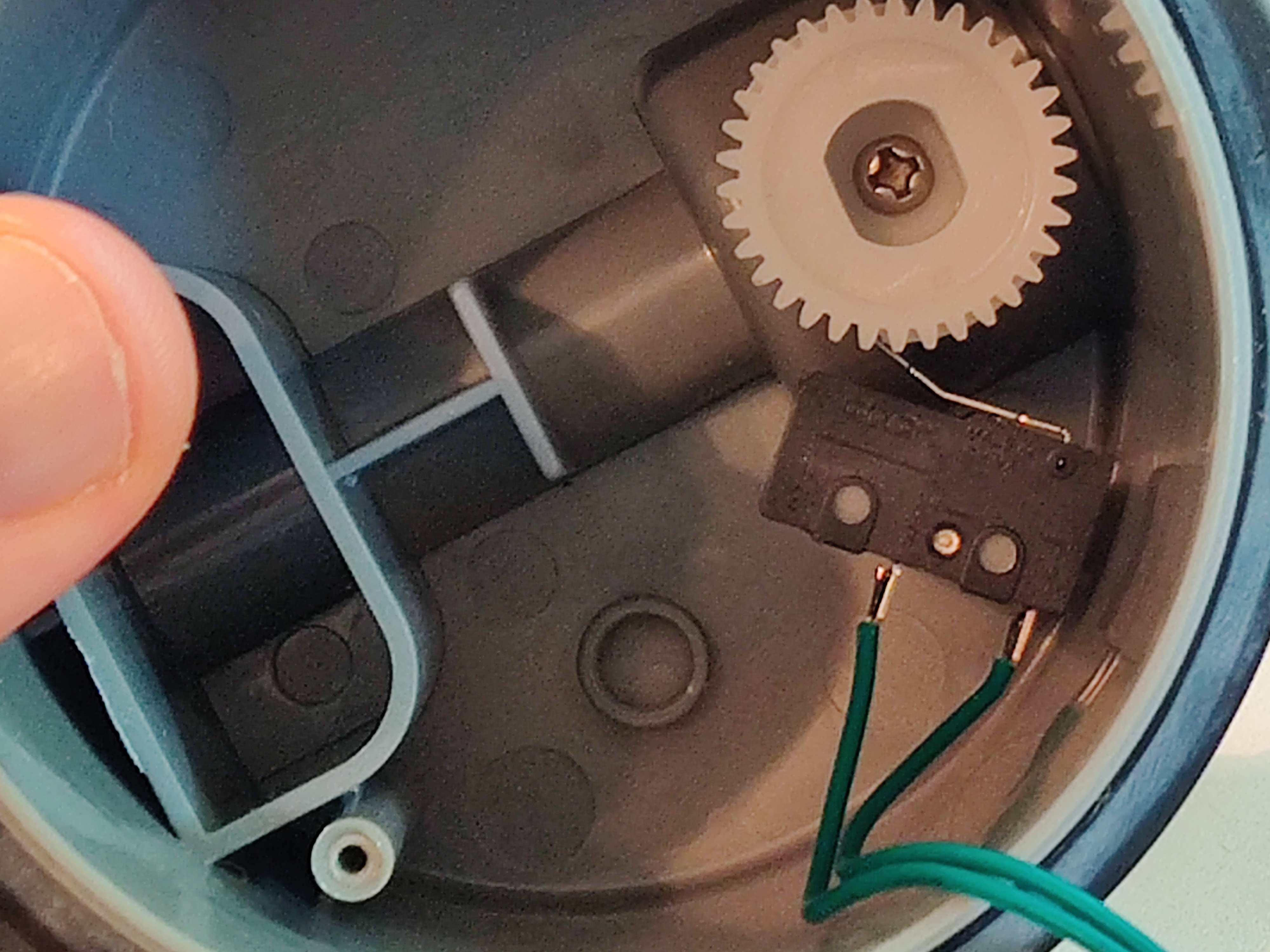
Notifying the systems chip when to stop rotating the motor. It'll make my life easier than tracking valves position.
I've also found that the Valve can rotate 360\*, making it easier to hack it, (There's an explain a bit further).
## Step 1, preparation
I worked on a fresh Ubuntu 19.10, so did some re-installing.
1. Arduino installed from [here](https://www.arduino.cc/en/Main/Software?ref=whatimade.today).
2. ESP32 support installed into the Arduino, from [here](https://randomnerdtutorials.com/installing-the-esp32-board-in-arduino-ide-windows-instructions/?ref=whatimade.today).
2.2\. I Checked If everything Is working, using the *wifiScan* tutorial from the esp32 examples. I **did** run into 2 problems:
2.2.1\. Received an `**ImportError** no module named 'serial'`. Solved that with `pip install pyserial`.
2.2.2\. Got an `arduino [Errno 13] Permission denied: '/dev/ttyUSB0'`. Solved that by `sudo chmod a+rw /dev/ttyUSB0`.
3. Setting Over-The-Air (OTA), using the **OTAWebUpdater** from Arduino examples. Thus enabling me to update ESP32 code Over-The\_air.
Now that we have Arduino installed, and fully operational ESP32, that can be updated over the air, we can continue.
## Step 2, figuring out things
Inside the automatic watering system there's an **DC** motor, rotating a valve.
I want to use the same motor, to rotate the same valve.
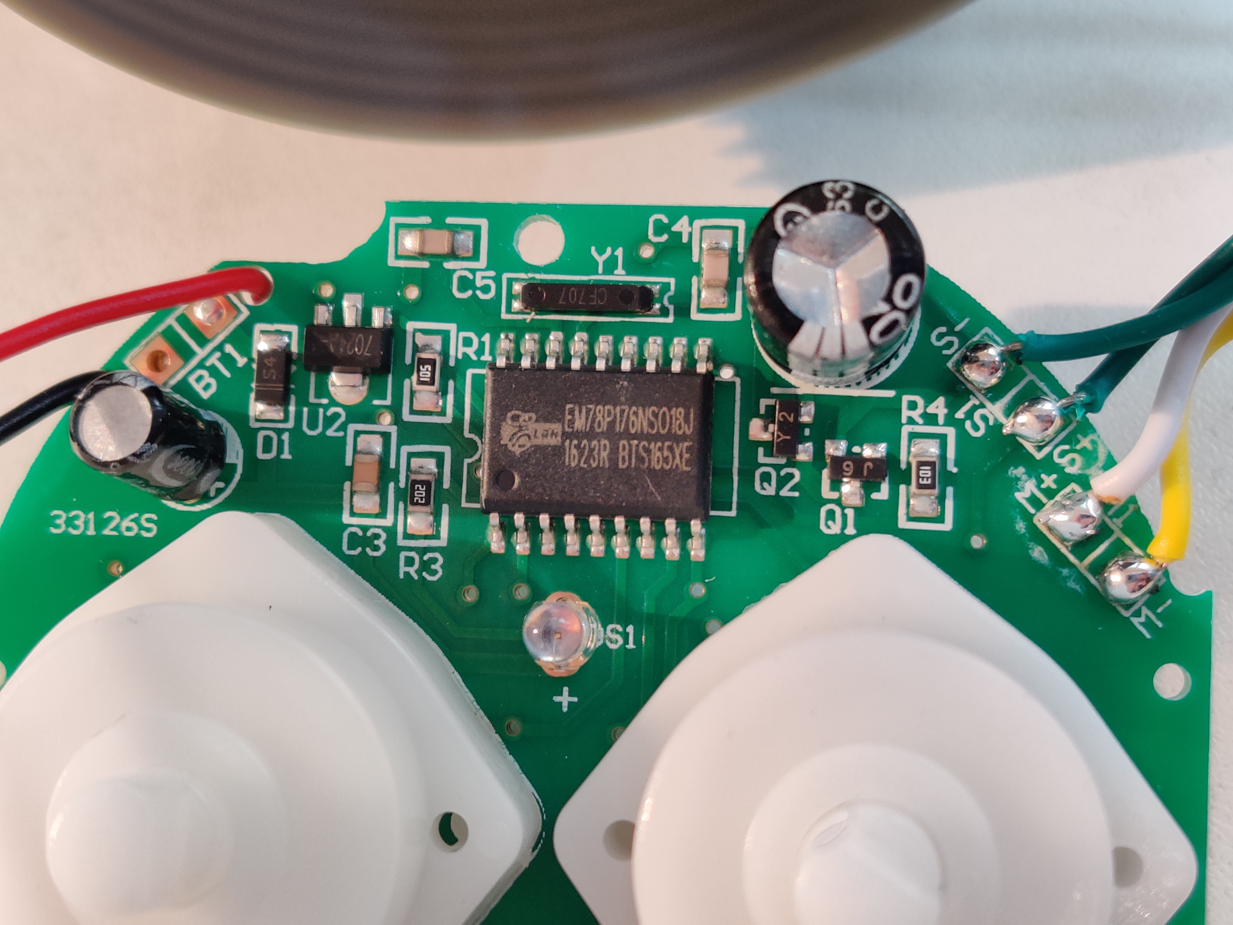
*Thing* is, to work with a DC motor, one need a DC driver, **which I don't have**.
So I thought to connect the ESP32 to the watering system on-board DC driver, **which I don't see**.
So I consulted with my MAKER friends (also authors in this *glorious* blog), and they suggested to use **MOSFET**, **which I don't know** what It is.
It sounds like the beginning of a joke, or a great post.
I'll let you decide.
### Before diving into learning new things,
I need to check if the motor can be operated on 3.3V.
So I've connected it directly to the ESP32 3.3v output, and **voia!**
Luckily, it does, now we can go deeper.
### A motor driver?, really?
Here is an example of one (the L298N):
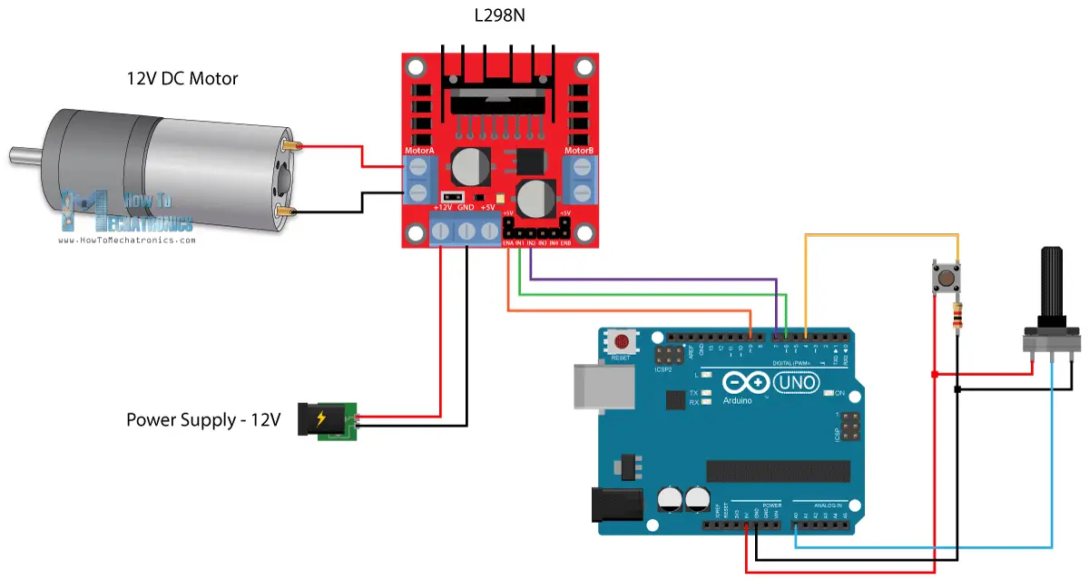
*Thing is*, DC motors run in various voltages, while the control is usually in 3.3v,5v,12v. So how one give commands using 3.3v to a motor that work on 60v? That's right - Using a driver.
One more thing about the DC driver - it can change the direction of the motor, all one needs to do, is to give the right command.
**Luckily**, inside my automatic watering system, the valve can rotate 360\*, so no need for the *bidirectional* rotation feature. I do need to control the motor though (e.g start & stop).
Iv'e tried to connect the **+** of the motor to a **GPIO** pin, and the **\-** to ground, then set this pin to **HIGH** in the Arduino. Nothing happen, but that was obvious, right? because we all know that the ESP32 GPIO pins can draw as much as **12mA**, which is no good for rotating a DC motor.
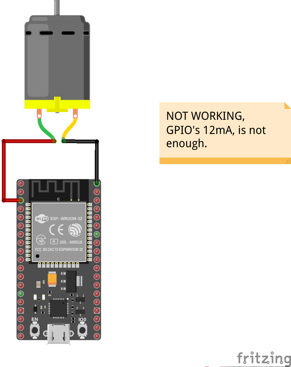
#### So, I need to operate a DC motor, using a **12mA** current?
Directly - that's not possible.
I need some **'thing'** that the **GPIO** pin controls, and in response, that **'thing'** controls the DC motor.
- At first I thought to use a **RELAY**, something like that:
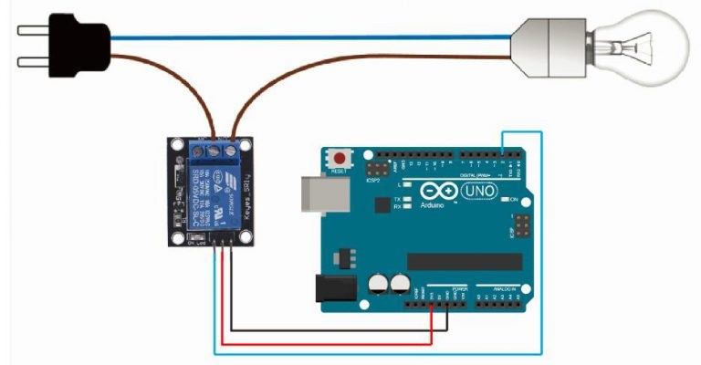
Although a relay use 3.3v to operate things that require much more voltage, I is a **binary** switch, there's **ON** state and **OFF** state.
**But what if I want to use some analog input/output that comes from much higher voltage than the GPIO can work with?**
Here comes the **MOSFET**..
### So, what is MOSFET?
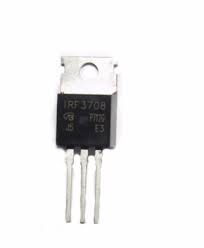
A **metal–oxide–semiconductor field-effect transistor**,
also known as the metal–oxide–silicon transistor (MOS transistor, or MOS), is a type of **insulated-gate field-effect transistor (IGFET)** that is fabricated by the controlled oxidation of a semiconductor, typically silicon.
The voltage of the covered gate determines the electrical conductivity of the device; this ability to change conductivity with the amount of applied voltage can be used for amplifying or switching electronic signals.
**The MOSFET is the basic building block of modern electronics, and the most frequently manufactured device in history, with an estimated total of 13 sextillion (1.3 × 10²²) MOSFETs manufactured between 1960 and 2018,**
[wikipedia](https://en.wikipedia.org/wiki/MOSFET?ref=whatimade.today).
#### Simply put,
Its a transistor, that change its conductivity, given some voltage.
Using this **MOSFET**, I could operate a 5V DC motor using the Arduino 3.3v gpio.
Nice. Right?
# A MOSFET, TADA!

A working example, using a mosfet:
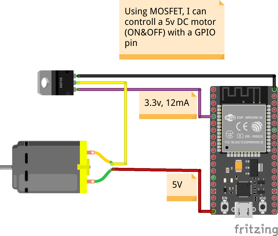
And a working proof:
I've set the **GPIO** pin to LOW, and the conductivity changed accordingly
### Knowing valve's position
Earlier, I've mentioned that there's a micro-switch, giving feedback about the valves location (mainly OPEN/CLOSE status).
Here how I have used it in my favor:
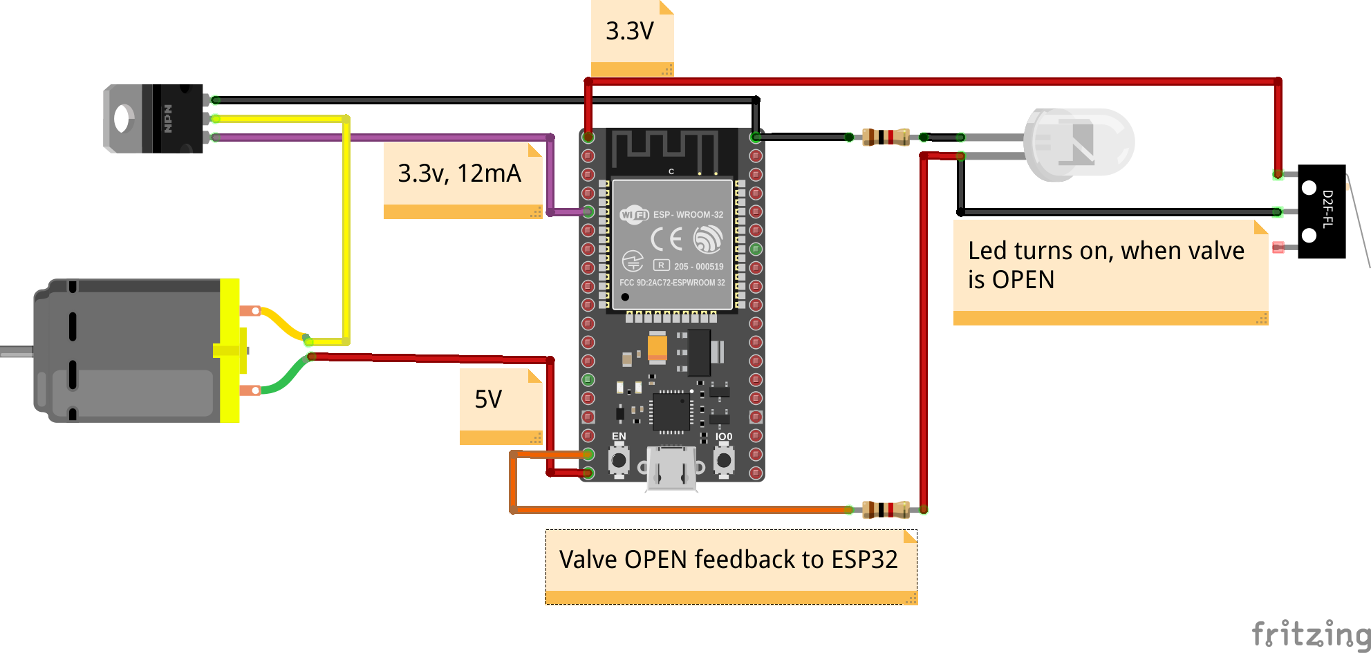
**Finally, I done with all the electronics. Time to write some code :)**
## Step 3, Adding functionality
We saw in the original plastic cover, that there are 2 rotating switches:
- **RUN TIME**
- **FREQUENCY**
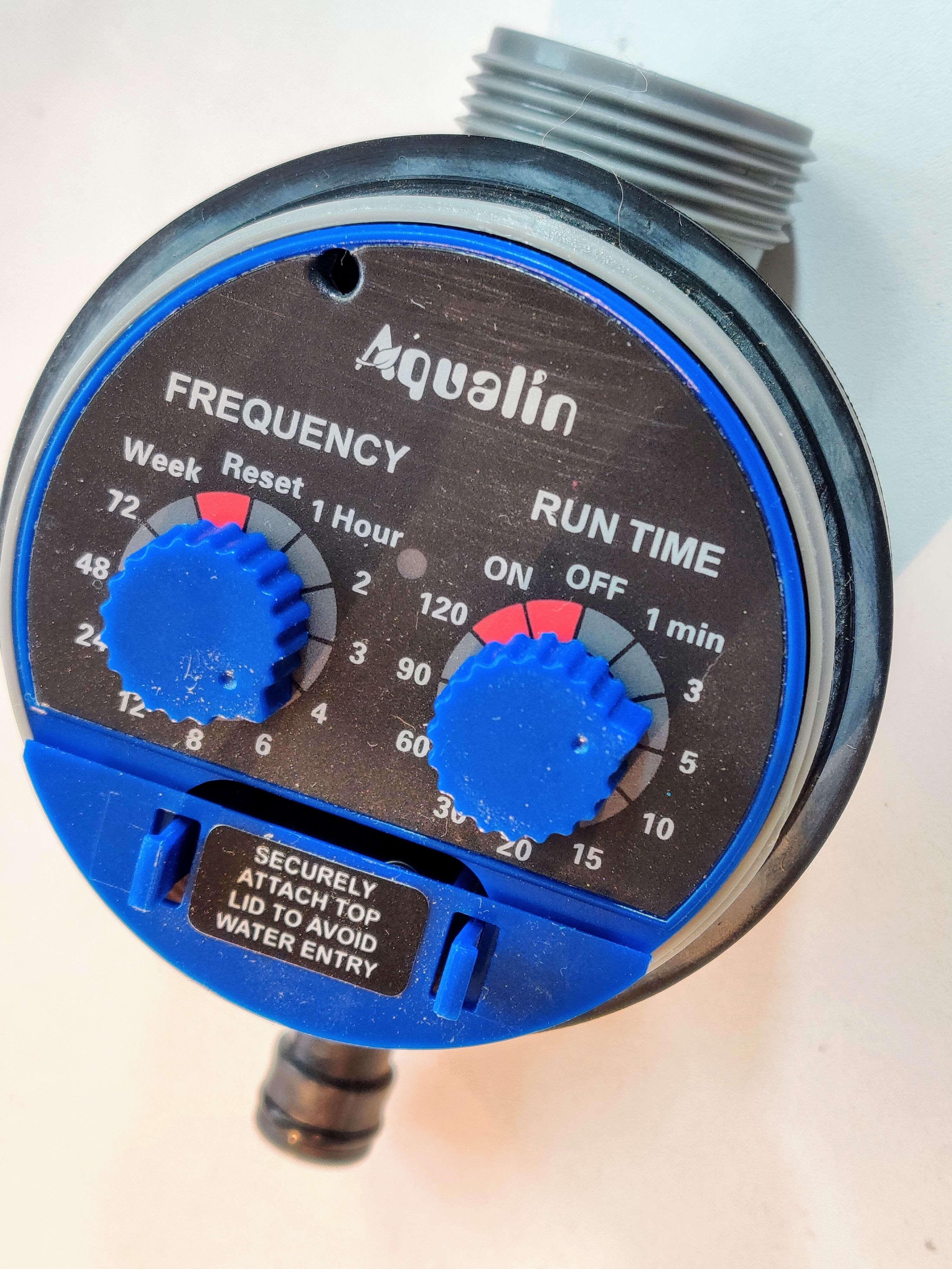
I kept these functionalities, just moved them from physical switch, to the *cyberspace* (wooo buzz word!):
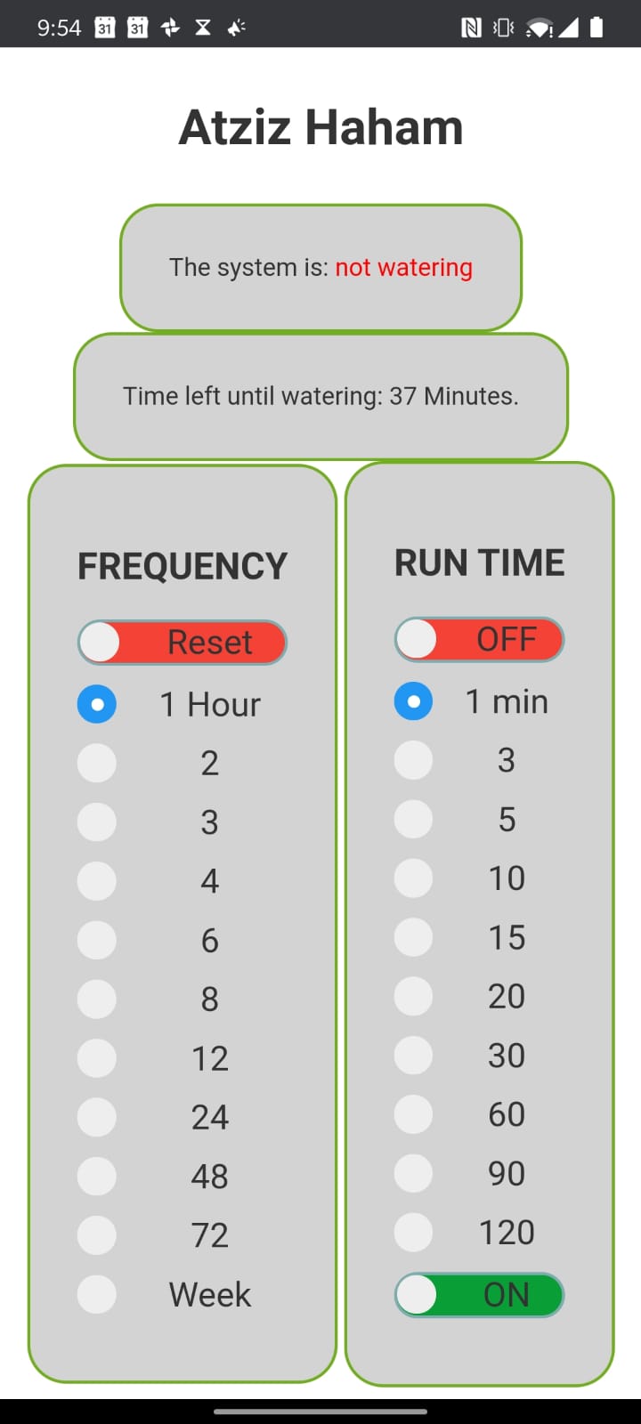
(**Atziz Haham**, meaning **smart plant** in Hebrew.)
### Lets break the code
([The whole code is in github](#github))
While this is not my first *rodeo* with ESP32 and an HTML web-server [(I also made the BabySleeper)](https://whatimade.today/babysleeper/), I did learned a lot!
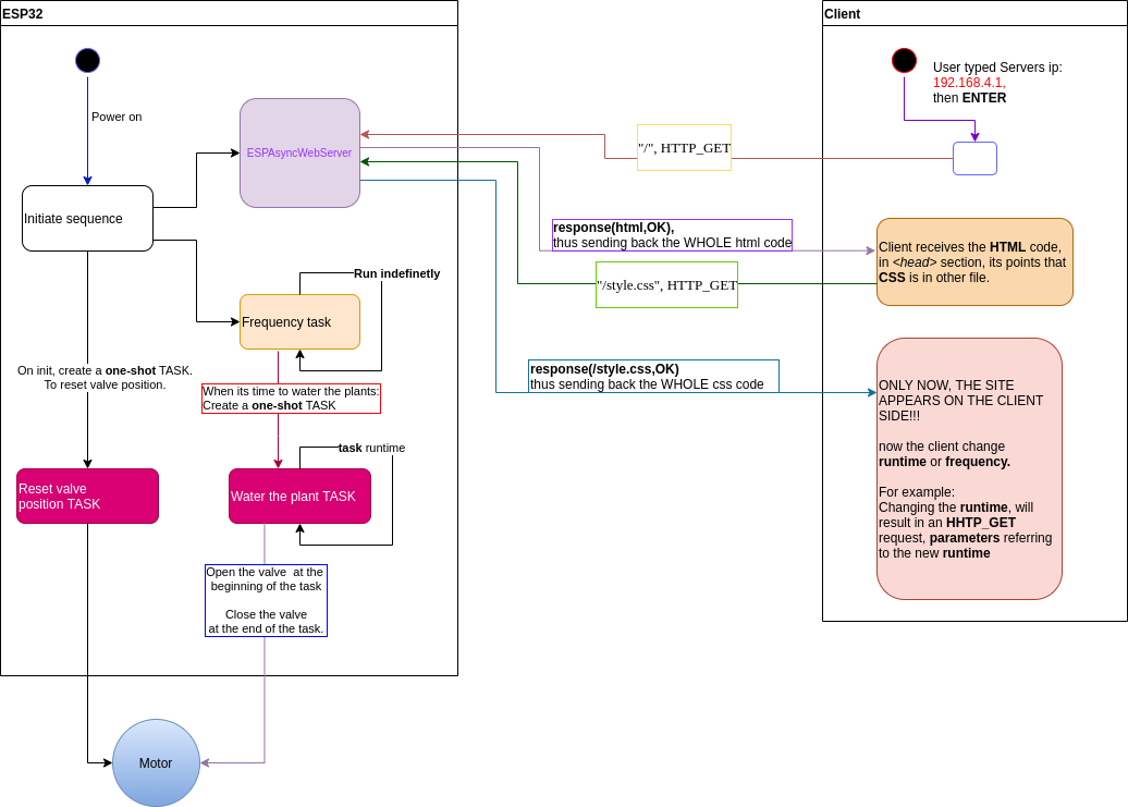
Lets break the code with a **BOTTOM-TOP** approach:
Its the projects architecture, to be able to water the plants for curtain amount of time, in intervals of some hours. That sound classic for the Arduiono's `loop()` function right?
Implementation could be something like that:
```c++
void water_the_plants(int runtime_duration){
openValve();
delay(runtime_duration);
closeValve();
}
void loop(){ // Run indefinitely
water_the_plants(runtime_duration);
delay(frequency_duration);
}
```
But its problematic, say I want to change `runtime` from 1 minute to 3, **while** the system is watering the plants. By default `water_the_plants()` is *non interaptable*, It should water the plants as much time as it needs.
**So what?! If the system is watering the plants, it is non responsive for user input?!**
#### That is a big NO NO in software design terms
It seems like `water_the_plants(int runtime_duration)` should run in a separate thread. So the system could water the plants **while** being responsive to user input.
Hence for the first time (*like, EVER*), I used Arduino's **Task**s.
Its a thread-like mechanism that can run in *parallel*.
#### Why *thread-like*?
By definition, a thread is not something that can be killed from the outside, for example:
```c++
void my_thread(){
while(1){
do_stuff;
}
}
void setup(){
thread *t = thread(my_thread);
t.start(); // that's OK
delay(1000);
t.stop(); // NO SUCH THING IN A THREAD!
}
```
If a program needs to do something after a thread is done, it needs to `t.join()` meaning:
## *Ill sit here, and wait until you do you*.
Meanwhile, Arduino's **Task** can do exactly that!:
```c++
BaseType_t xReturned;
TaskHandle_t xHandle = NULL;
xReturned = xTaskCreate(
runtimeTask, // Function that should be called
"Watering task", // Name of the task (for debugging)
1000, // Stack size (bytes)
NULL, // Parameter to pass
1, // Task priority
&xHandle // Task handle
);
// Kill runtimeTask if it's running
if( xReturned == pdPASS) { // If the task was created successfully then pdPASS is returned.
vTaskDelete(xHandle); // KILL THE TASK FROM OUTSIDE OF IT!
}
```
#### That was a brief intro to threading and Arduino's task's
Now, we can continue with designing thoughts.
- I want to have a server running on the Arduino, this server will do the following:
- Send the clients valve status (open/close), and time left until next watering.
- Receive from client RUNTIME & FREQUENCY requests.
**This server should also run in *parallel* to the watering function**. Luckily, there's an [ESPAsyncWebServer](https://github.com/me-no-dev/ESPAsyncWebServer?ref=whatimade.today), that do exactly that.
Here is how I used it:
The server work on "HTTP-GET" requests, that are being sent from the client to the server, with the *url* telling from where the client sent the "HTTP-GET".
For example:
```c++
server.on("/", HTTP_GET, [](AsyncWebServerRequest * request) {
request->send(SPIFFS, "/index.html", String(), false);
});
```
This line tells the server that when it receives a **HTTP-GET** command, from the *url* `"/"`, then it sends back (`request->send()`) the **SPIFFS** (that contains the html itself).
So in order to send the clients **valve status (open/close)**, and **time left until next watering**:
```c++
server.on("/isSystemWatering", HTTP_GET, [](AsyncWebServerRequest *request){
request->send_P(200, "text/plain", String(isSystemWatering).c_str());
});
server.on("/getTimeLeft", HTTP_GET, [](AsyncWebServerRequest *request){
request->send_P(200, "text/plain", String(time_left_until_next_watering_min).c_str());
});
```
All the above was **server side**.
#### How does it look like in the client side?
An html skeleton should look like that:
```html
// Site graphics declarations (i.e fonts, colors, libraries etc)
some-definition
some-more-definition
some-css-declarations (can be in a separate CSS file)
// How the site will look (i.e photo locations, paragraphs filled with text etc)
some-headers
some-text
some-photos
some-paragraphs
// Another example of things inside the BODY:
```
In the client's **html**s body section there's this line:
```html
```
And in the **script** section there's a function:
```c++
function isSystemWatering( ) {
var xhttp = new XMLHttpRequest();
xhttp.onreadystatechange = function() {
if (this.readyState == 4 && this.status == 200) {
if (this.responseText == 0){
document.getElementById("isSystemWatering").innerHTML = "not watering";
document.getElementById('isSystemWatering').style.color = "red";
}
else{
document.getElementById("isSystemWatering").innerHTML = "watering";
document.getElementById('isSystemWatering').style.color = "blue";
}
}
};
xhttp.open("GET", "/isSystemWatering", true);
xhttp.send();
}
```
**Break down:**
- At first, a new `XMLHttpRequest()` is created.
- Then I attached a function that will be **called when the server responds**: `xhttp.onreadystatechange`.
- The attached function will do the follow:
- Check if the server respond with *"OK"* (200): `if (this.readyState == 4 && this.status == 200)`.
- If it does: update the clients html, where there's an element with an `id="isSystemWatering"`, with the corresponding text.
- Finally I will open a **"GET"** request, with the `url = /isSystemWatering`.
- And send the request to the server.
The logic is being reused for other purposes, but the main idea is the same.
This is how I implemented all the functionality of the server.
**And last but not least** (as promised, a BOTTOM-UP approach):
## Project's high level overview:
---
## Project summary
I love messing with Arduino.
At the beginning, it was all about toggling a LED on & off,
later on, I used Arduino to read sensors (gas, temperature & humidity sensors),
then I used the ESP32 (also, Arduino) as a server.
Today I've learned all about **Tasks**.
It seems that every time I mess with Arduino, I get closer to the **bare metal** of things.
**And I love it!**
Cheers, Gal
Code *n'* stuff - [my github](https://github.com/GalBrandwine/SmartWateringSystem.git?ref=whatimade.today)