This post is different from anything we’ve published before. It’s an explanation of how we created one of our most ambitious projects to date - and it’s also a call for help.
Working on the project opened up incredible possibilities for the rapid development by the Community of Makers of specialised and inexpensive medical aids that would be far too expensive, (in time and money), for regular people with urgent needs. Read on and you’ll understand.
The Project
This post describes a project that was aimed at helping a child with developmental disabilities. Time was critical and all help was greatly appreciated. In short, we created a device to improve a child's locomotive motor skills - i.e. to encourage him to crawl. The device was constructed in a very short timeframe and is far from perfect - yet it still made an impact. Right now, I don't have time to keep supporting the project, but would be happy to see it developed to a more professional level with the help of our community. If you want to help improve the world, and have knowledge in robotics, programming, engineering, medicine or medical tools, please consider contacting us and contributing to upgrading the device.
Contact email: whatimadetodayblog at Gmail (Not writing the address to avoid spambots).
Please note: The writer is not a medical practitioner or a patent attorney, and disclaims any warranties that the devices described herein are medically safe or effective, or that they are free from infringing any patent or other proprietary rights.
Thanks to all the people who helped bring the project (and this post) to life. I received invaluable help in building, programming, testing, advising, supporting and proofreading. My sincere thanks to: Ross K., Danny W., Yotam P., Michael S. (and his two-year-old daughter), Michael D., Batia A., Zvika G., Efrat S., Bill F., and the Gemsense team.
Thanks,
Amir
Background Story
Around March 2016 I received a phone call from a father whose child had developmental disabilities. He found me through this blog and wanted to share his story and ask for my help. His son, two years old at the time, had not yet learned to crawl. Several attempts to help the child had been unsuccessful. After consulting a physiotherapist, they concluded that they needed to work on positive reinforcement of the brain - so that the child would learn the connection between hand movement and physically moving forward/backward.
The father had in mind an apparatus connected to the child's arms that reacts to hand movements and moves the child around. He had started by looking for a commercial device or a university that would agree to build what he needed - but he met constraints of time and money. Most of the places capable of creating the apparatus would need thousands of hours of "engineering and development time", so they placed the price tag of more than a million dollars on the project. They also estimated it would take more than a year of work. These figures shouldn't surprise anyone, since building a professional product involves a lot of work, including development and final approval. I don't know if the father was willing to invest this amount of money, but the time issue was way more critical. According to the physiotherapist, if there was no improvement by the time the child reached the age of three, irreversible damage was more likely.
So the father decided to aim for a less professional device - one that could be built in one or two months. That's when he found this blog and asked if I could construct such a device. I hesitated at first; it seemed like a great deal of responsibility - but it was a noble cause and I felt, on a basic human level, it's important to help when we can. After consulting some friends, I explained that we had the ability to create the device in a short time, but he should understand that it would be a "prototype", and we couldn't take responsibility for any damage it may cause. (This was backed up by a legal disclaimer). I explained we understood the need, and that we would build it while taking the best safety measures we know. As it was for a worthy cause, we would ask only for the cost of materials (roughly 500 dollars). The father told us that if there was even the slightest chance of helping his son, he would go for it. He considered our terms understandable. I think every parent would think the same - though I'm not sure every parent would be brave enough to take the risk.
The moment we got a green light we started work. About two months later the device was working. With our background support the child started using it. We fixed a few bugs and optimized the software on the go. Here's a short video of one of the first uses of this device, approved for display by the family:
The events in the video are explained below in the "General Procedure" section. A flow chart illustrates that we looked for a stimulus that would increase the boy's attempts at crawling. The motion of the device would be a positive reinforcement for the child's behavior. In the beginning it strengthened his attempts to initiate movement for crawling, but eventually it shaped specific movement and emphasized the motivation operation for practicing new motor skills.
Why Document? Can Open Source Apply Also to Medical Uses?
Skipping to end of the story - we met at the beginning of September 2016, and I could see that the child was crawling a little. It was hugely satisfying. I can't say for sure that our device was the main cause of the child's progress, since it wasn't the only method used. It's possible the more common methods made the largest contribution, but there's also the chance that our apparatus helped too. If that's the case, it's wonderful.
By this time, the child no longer need our device and the physiotherapist suggested that perhaps other parents would wish to use it. (This would help provide statistics about the efficiency of the device). She also suggested improvements - some of which I'm capable of doing, and some I'm not.
Unfortunately I don't have any more time to give technical support to the platform. In addition, some improvements are beyond my technical ability. This led me to think about reaching out to more people with this story, in the hope they may want to help support this, or similar projects. Then I started wondering about the entire process as a concept: We developed a working prototype for a medical tool in about 1/10th of the time it should take, at about 1/100th the cost, and with less human resources than it should require. Obviously this device will never obtain FDA approval, and for that reason, it will never be recommended for use by medical practitioners. But perhaps with the help of the Maker Community it can actually become a cheap device for the less financially fortunate? Or say it can't be recommended by professionals, but receives a hundred or thousand reviews by appreciative users - wouldn't that encourage other developers to lend a hand?
The answers to these questions are exactly the reason so many people use open-source code today. It's the reason people prefer Linux over Windows, or coding in Python over Matlab. Crowd Wisdom is a powerful thing and there may be room for it in the medical world for those suffering from a rare condition where no company considers it profitable enough to develop a device to help.
For that reason we decided it's important to document the process of our construction. We received the father's permission to publish the story with accompanying videos - and of course, to share the entire design and code.
The Documentation
General Procedure
I'll try to keep it as simple as possible! How does this apparatus work?
The basic components:
- Gem sensors - Very small and low-powered sensors incorporating an accelerometer, gyroscope and Bluetooth.
- Computer - current code runs on Windows but can be modified easily to Mac and Linux. It can also run on tiny, inexpensive computers like the Raspberry Pi.
- 2 x Arduino
- 2 x NRF24L01 - 2.4GHz communication module.
- 2 x LM1117 voltage regulators (In case you don't already have them on the Arduino boards)
- 2 x Motors - AndyMark NeveRest 40 Gearmotor (am-2964a)
- 2 x wheels and holders
- 2 x L298 Motors Drivers modules
- 12V 1-2 AH Lead-Acid battery with a charger.
- Additional small electronic components - resistors, capacitors, fuses, wires
Position of the components:
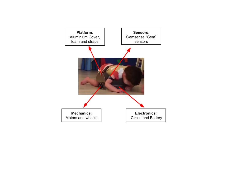
The procedure:
- The child lies on the platform, with one Gem sensor strapped to each arm. (Other parts of the body can be used in future development).
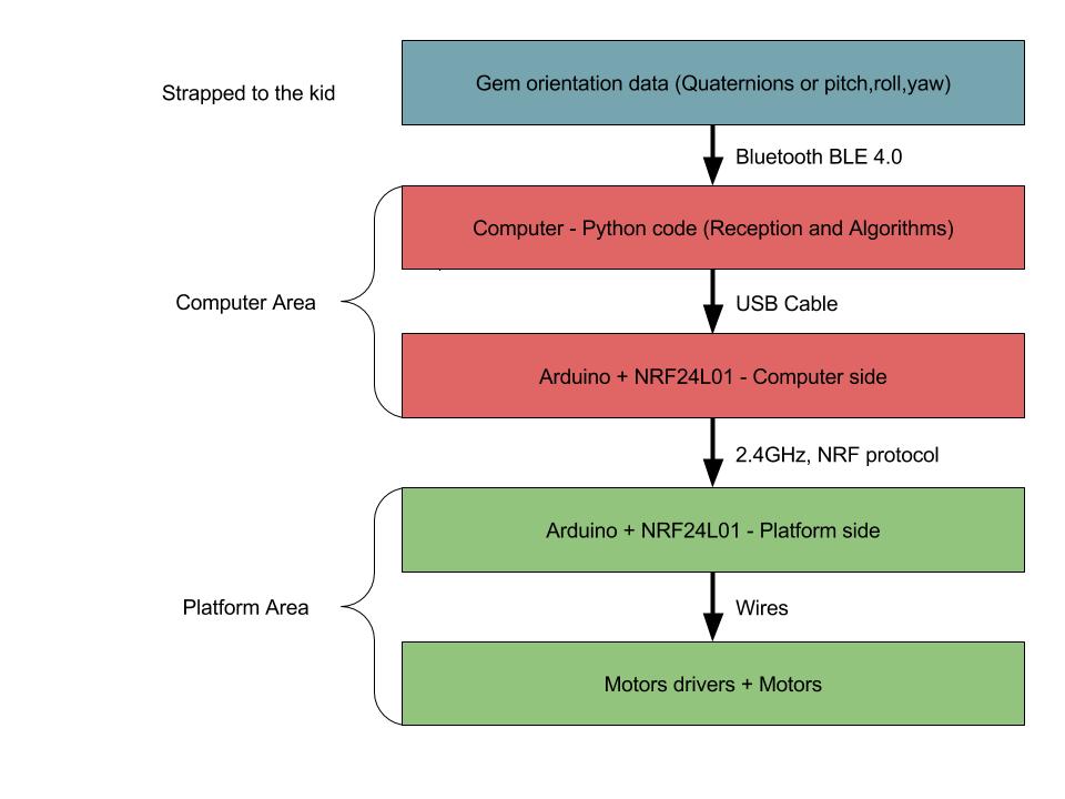
- The Gem sensors transmit the arms' orientation data via Bluetooth BLE to the computer.
- The computer runs a Python code to gather the information, translates it into readable data of the arms' elevation, and stores the data in a time series database. Then, the computer analyzes the time series and detects pre-defined changes in the elevation over time - which signals there has been proper movement of the child's arms.
- If a positive detection is made, the computer sends a serial signal to an Arduino connected to its USB port, and the Arduino forwards the signal to a second Arduino on the platform via two NRF24L01 modules.
- The moment the Arduino on the platform receives a signal, it creates and transmits two PWM signals to the platform motors (through their drivers), causing them to move the platform gently for a very short period of time.
- The entire process is constantly recorded.
Before going into the details of each above bullet, I'll jump straight to the last one - It is crucial to record all data going into - and out of - the computer. This greatly helps to improve the code and fix bugs even after delivery of the device.
Our method of work after delivering the device was to let the father and child work with it while they filmed the entire process. They then sent us the full video and the sensors' logs with time-stamps indicating where they weren't satisfied with the results. (The platform should have moved but didn't, or it shouldn't have move but did). With this information we ran a simulation of the logs up to the time-stamp to see why it didn't react as expected. After examining several issues, we were able to fix bugs or optimize algorithms to remedy a problem - while ensuring that the changes didn't affect the rest of the logs. (This is a standard and robust procedure that ensures software improvement on every release).
The Platform
Before anything else, we started by building the platform. We obtained the dimensions from the physiotherapist and started work. We began by finding a bent aluminium plate that fitted the required dimensions.
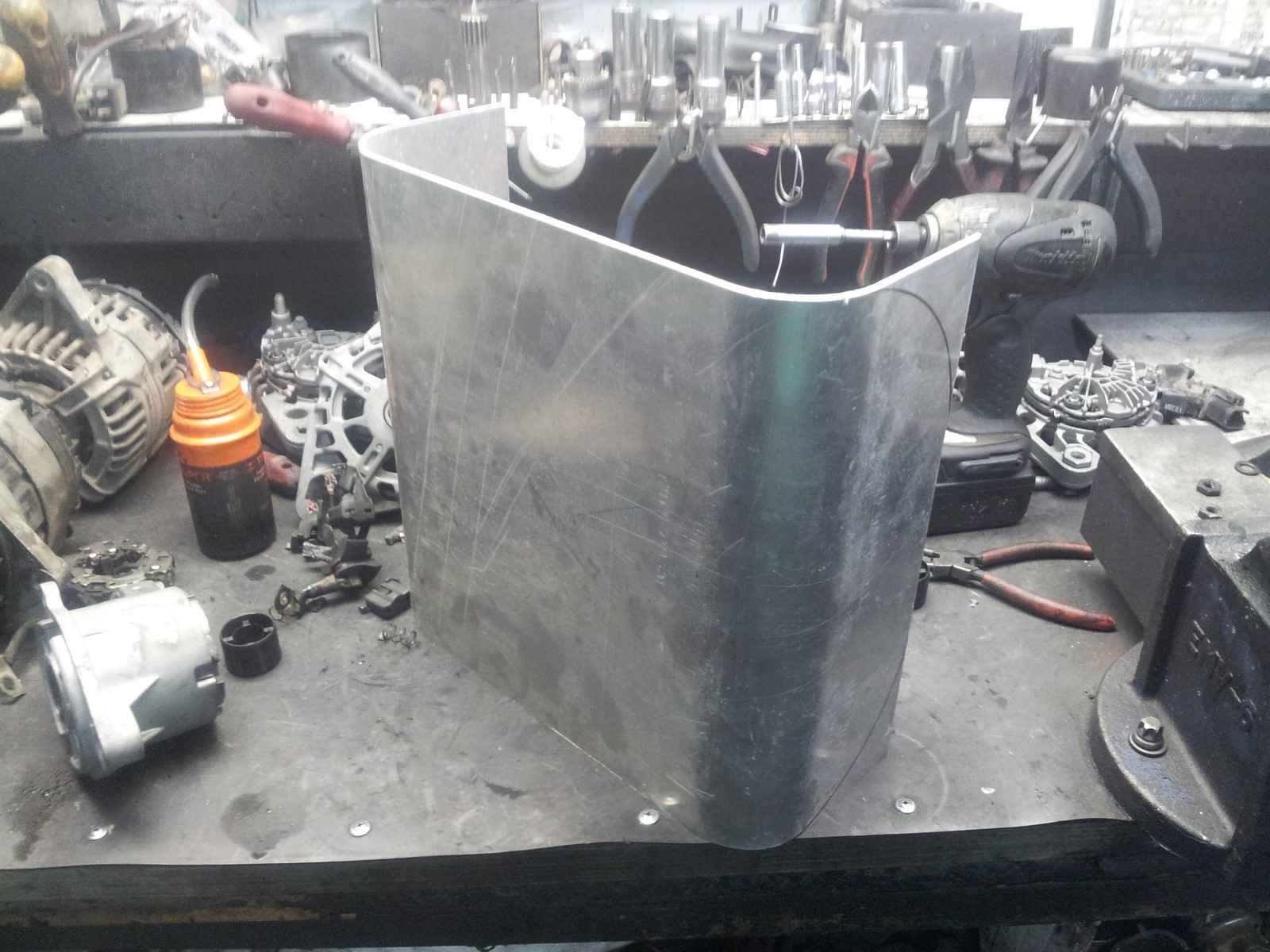
Then, we cut the plate and narrowed it slightly at the front and back to create space for the hands and legs:
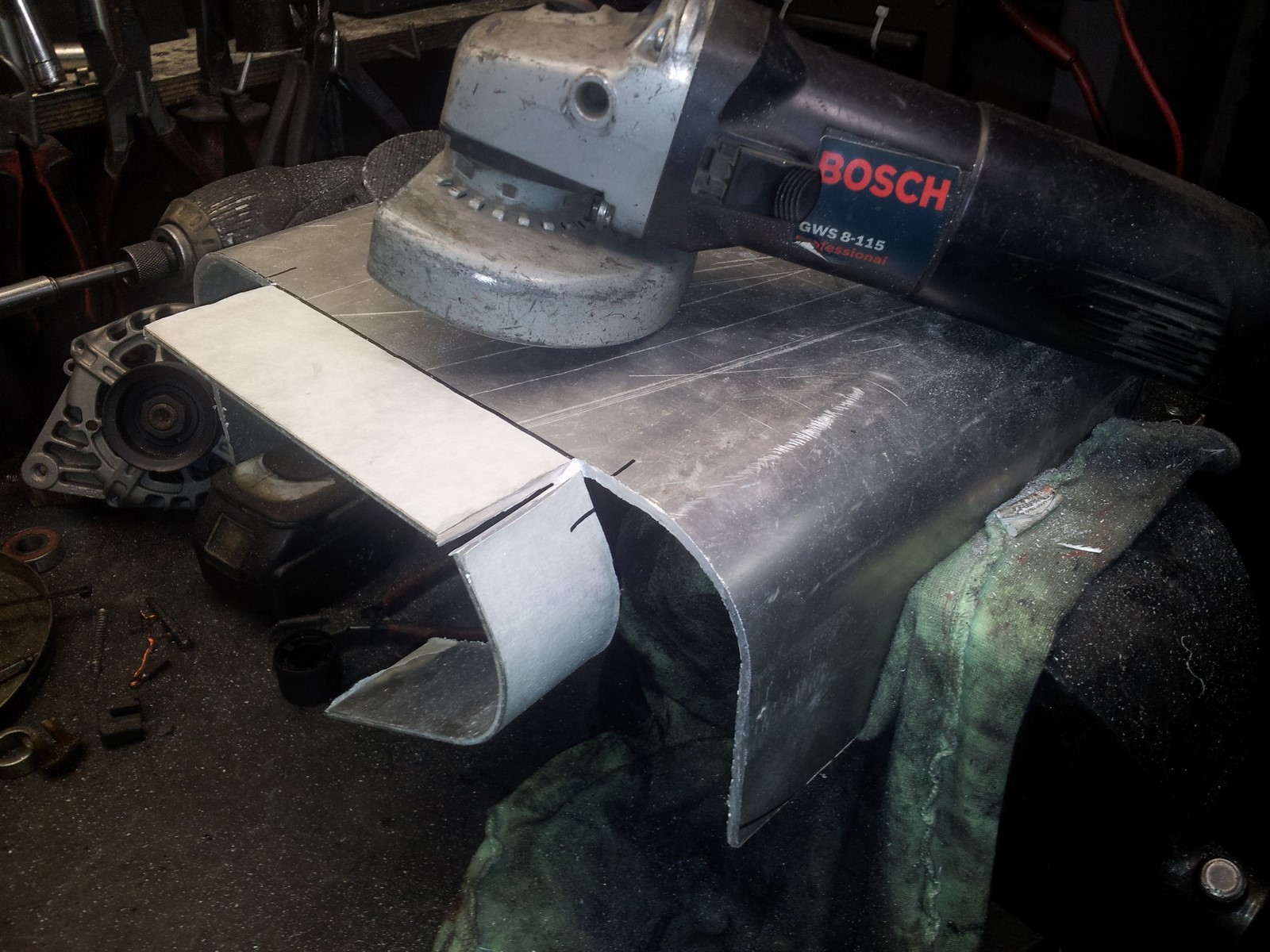
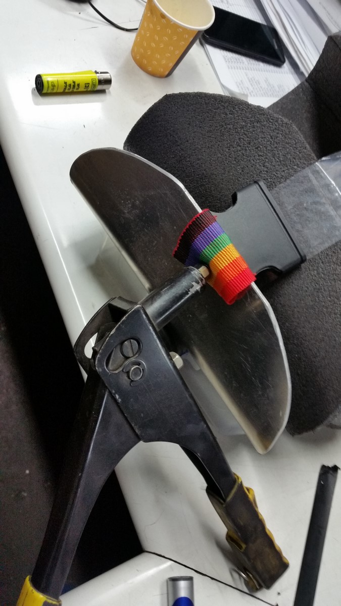
Next was polishing:
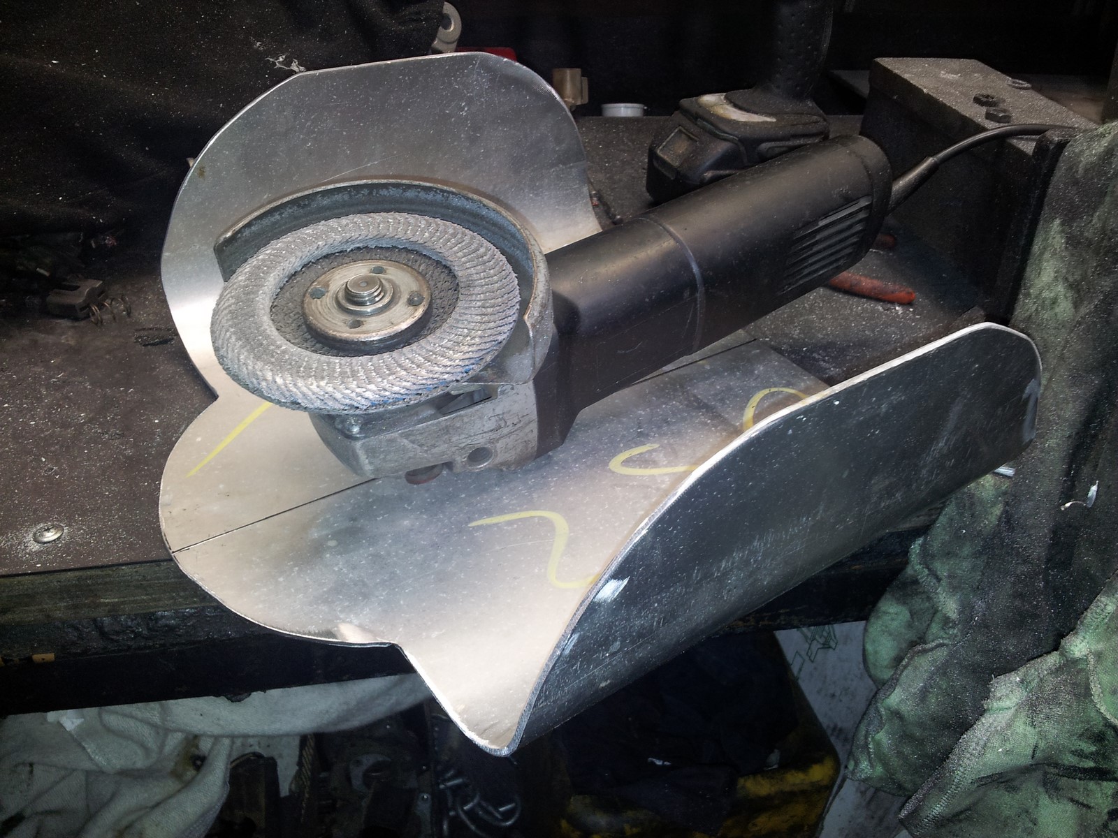
Next, attaching the motors in the right places. Notice that the motor shaft is not centered. This was very helpful allowing us to adjust the platform height after finishing the build:
Then, wheels were attached to the platform:
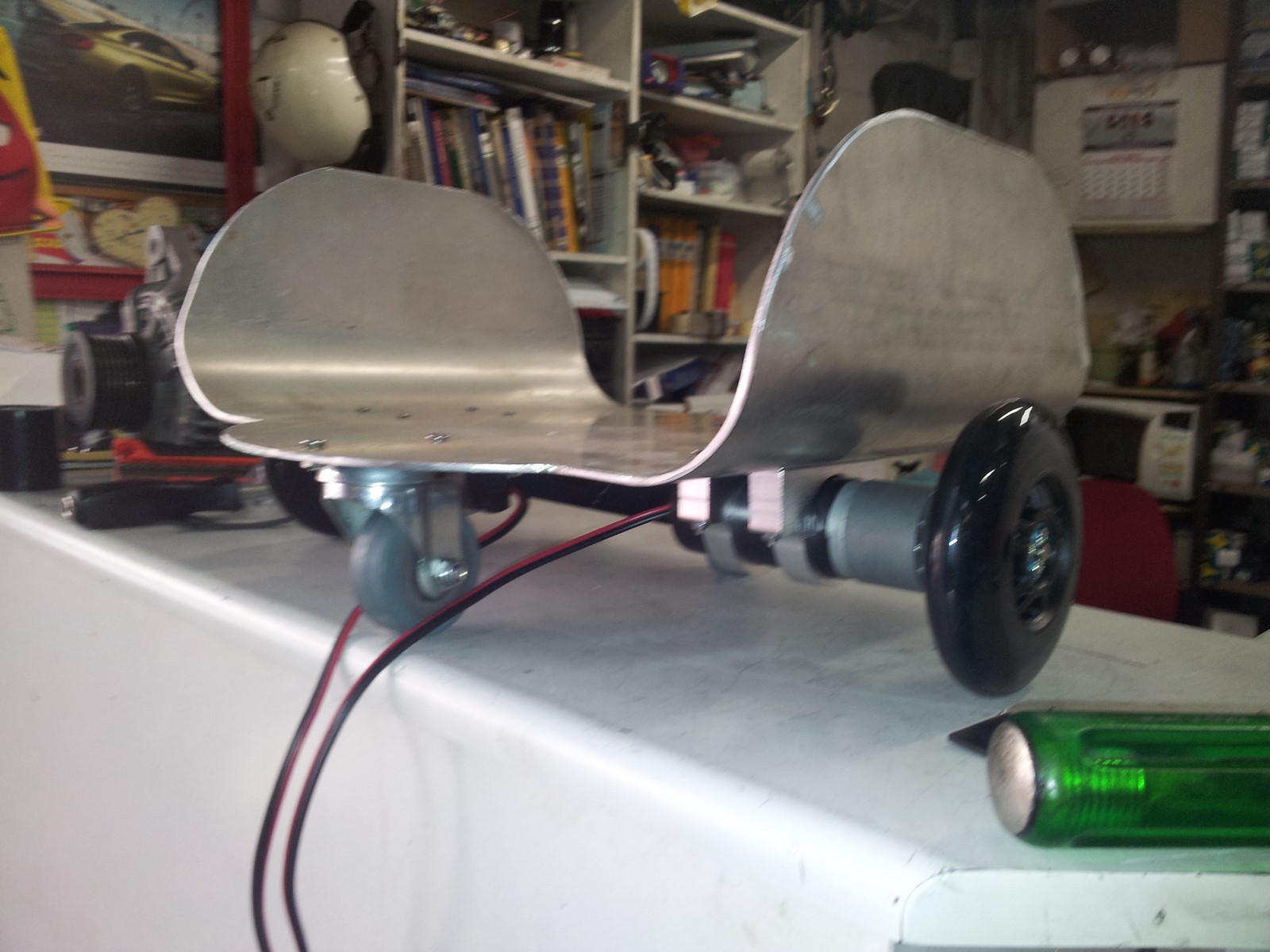
Note: The caster wheels were later removed since their circular movement made the platform unexpectedly change direction. We ended up not needing them and replaced them with the rubber pads shown below.
Finally, some hard foam was shaped for the platform to make it comfortable. We installed several layers to allow us to play with the platform height.
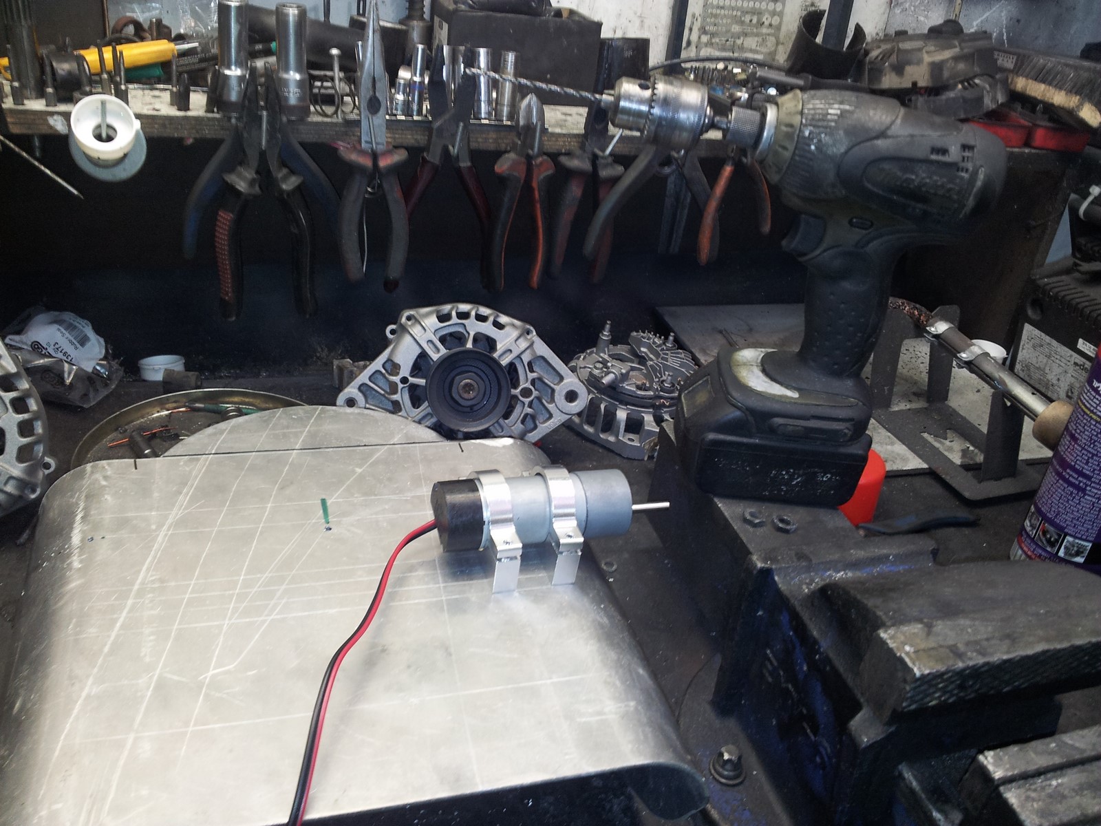
The next stage was testing to see that the platform was the correct size, and that our motors were sufficiently powerful. To check the size, we met the father and child, measured the apparent comfort, width and height and made corrections later in our workshop. To test the motors, we took an old computer weighing about the same as the child (10Kg) and placed it on the platform. We connected the motors straight to the computer with some pre-made motor drivers and made sure it moved freely.
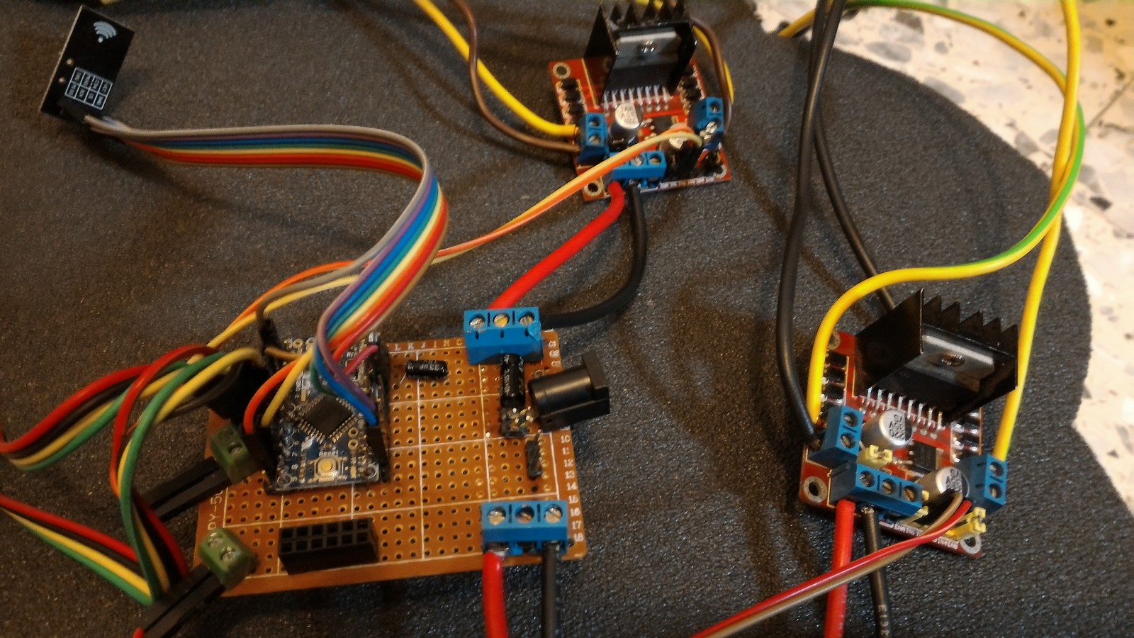
It was time to move on to the electronics. Here's a sketch of the components on the platform: (I'll try to make a real electronic sketch when I have more time).
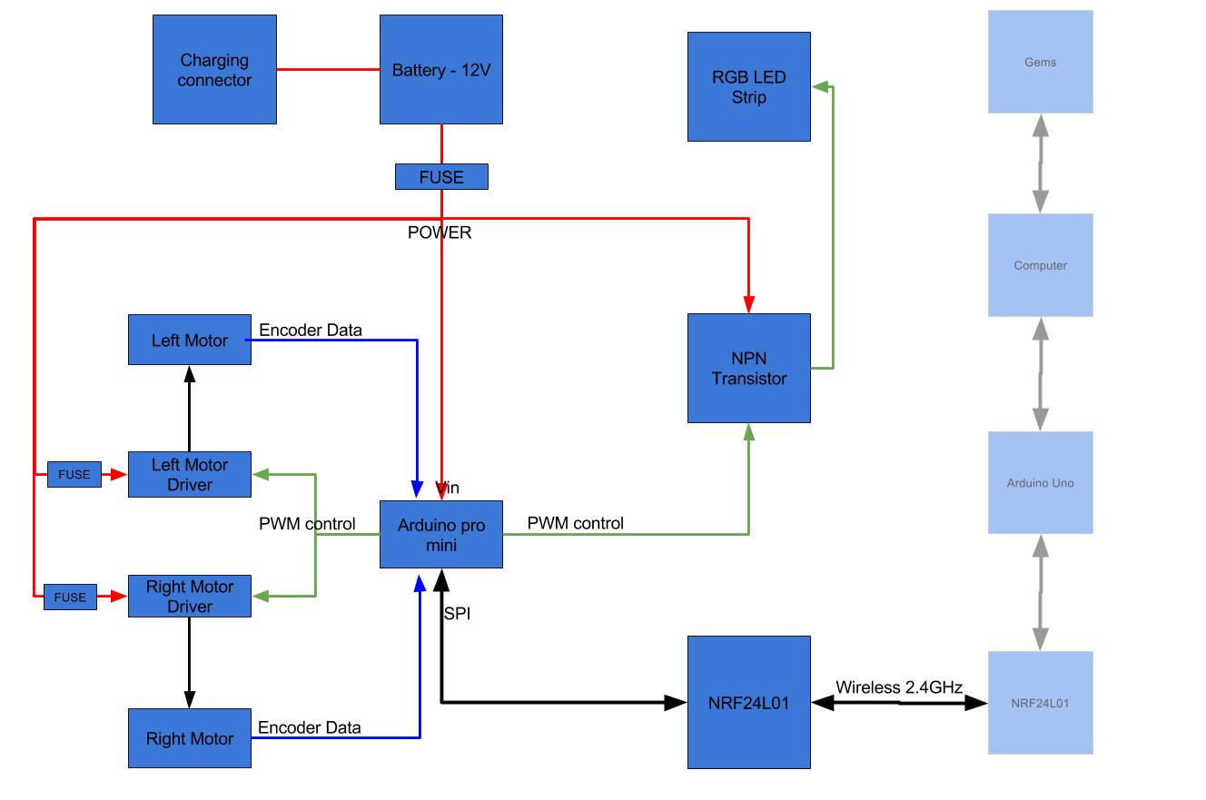
The transistor and LEDs are optional; we added them to create a blink every 10 seconds to allow us to synchronize with the recorded video. The motors are regular DC motors with encoders, just like I described in my scorbot project.
When powering a DC motor, it is very hard to precisely control its speed - so controlling two wheels with DC motors to make the platform go straight is basically impossible without receiving feedback from the motor. We used encoders because they supply precise information about the wheels' movements. This allowed us to play with the motors' speed to synchronize the encoders' values. That ensured the wheels always moved in a similar way and the platform moved exactly the way we wanted.
Each of the motor drivers mentioned above can control two DC motors at currents up to 2A. Our motors, with the expected weight on the platform, would draw a bit more than 2A. This could burn the drivers. The solution suggested in the drivers' datasheet was to use one driver to control one DC motor and connect the wires in parallel - making it possible to draw around 4A from the power source.
The Arduino code can be found on Github, and is based on similar code I wrote for a model car, described on the post about our Geekcon pets project. The original code had many unnecessary functions (e.g., it can drive in any direction, not only forward). The important parts of the code:
Listening and receiving wireless data through the NRF24L01:
 byte data[Mirf.payload];
  if (!Mirf.isSending() && Mirf.dataReady()) {
    Mirf.getData(data);
Adjusting the motors' power using the encoder values:
      gap = (int)(encLeft - encRight);
      if ( encLeft > encRight && encLeft - encRight > 127 ) {
        realPowerLeft = 0;
        realPowerRight = rightPower;
      }
      else if ( encRight > encLeft && encRight - encLeft > 127 ) {
        realPowerLeft = leftPower;
        realPowerRight = 0;
      }
      else {
        if (gap > 0) {
          realPowerLeft = leftPower - 2 * abs(gap);
          realPowerRight = rightPower;
        }
        else {
          realPowerLeft = leftPower;
          realPowerRight = rightPower - 2 * abs(gap);
        }
      }
Safety measures: Lowering the motors' power before stopping, and stopping completely if the motors don't receive any data for more than a specified time (in our case - 600 milliseconds):
 if ( (millis() - TimeNoComm) > DT2STOP)
  {

    if (dataDirLast >= 1 && dataDirLast <= 4 && (millis() - TimeNoComm) < 3 * DT2STOP ) {
      leftPowerLast = updatePower(leftPowerLast, 0,false);
      rightPowerLast = updatePower(rightPowerLast, 0,false);
      realPowerLeft = abs(leftPowerLast);
      realPowerRight = abs(rightPowerLast);
      switchData1(dataDirLast, true);
    }
    else {
      motor_stop();
    }
...
}
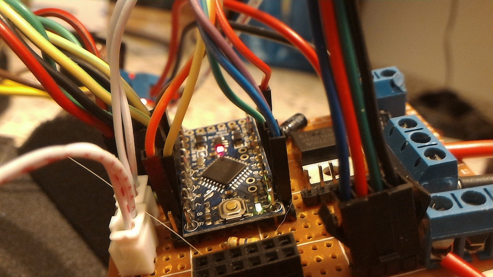
Here's the first prototype of the circuit , without the LED part.
Later we added the transistor and LEDs, and added connectors to each of the wires.
Finally, and as described in the sketch, we added fuses of 8 and 4 amps at all places that might expect high current. The fuse next to the battery would protect the entire circuit should shorting occur. Without the fuse, the entire platform potentially could go up in flames! (Samsung, take note!)
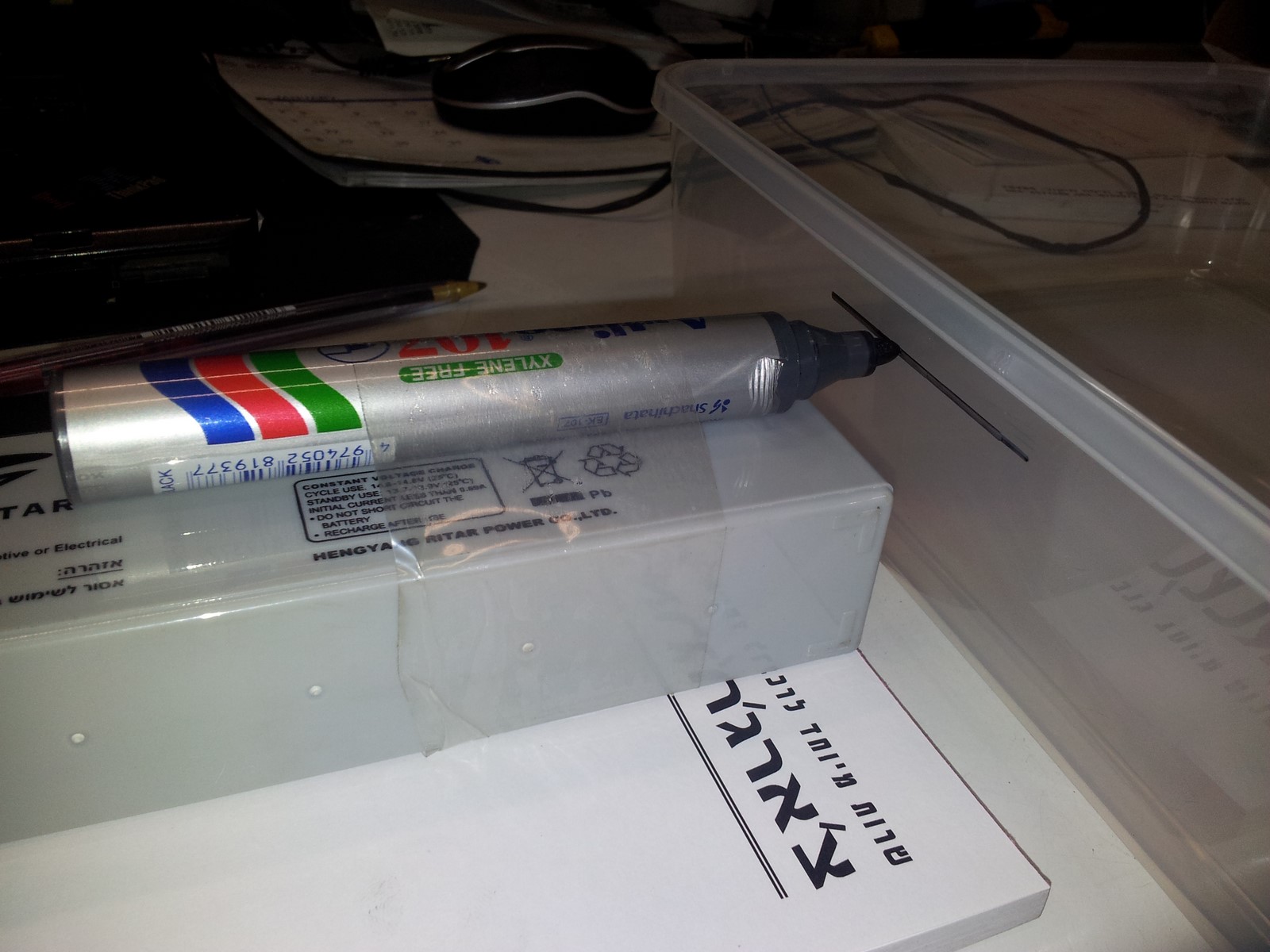
Lastly, we had to select a battery. We chose a lead-acid battery mainly because it is the easiest and safest to use in terms of charging and reuse, and of course, it met all of our demands. The disadvantage of the lead-acid batteries is that it is very heavy (same chemistry as your car battery), but weight wasn't an issue as the motors were aimed for much heavier lifting. On top of the platform and below the foam we added a charging connector and a three-state switch - Off, On, Charging. We added the third state since when charging a 12V battery, we need to supply a voltage of 14-15 volts. If this voltage were to reach the Arduino it would destroy it.
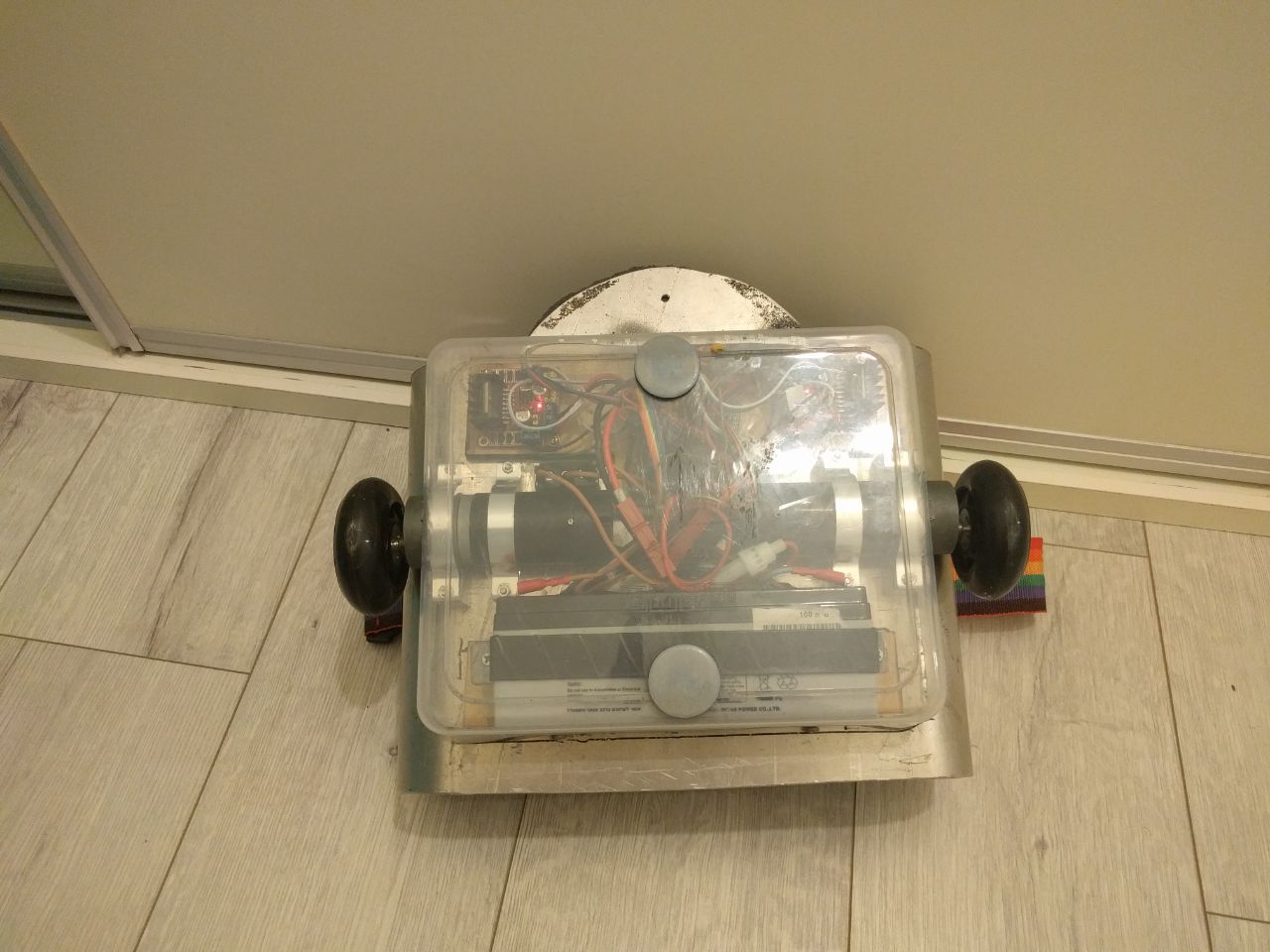
After the electronics were ready, we attached our circuits to the bottom of the platform. We used plastic casing for this, cutting it to the height of the bulkiest component - the battery:
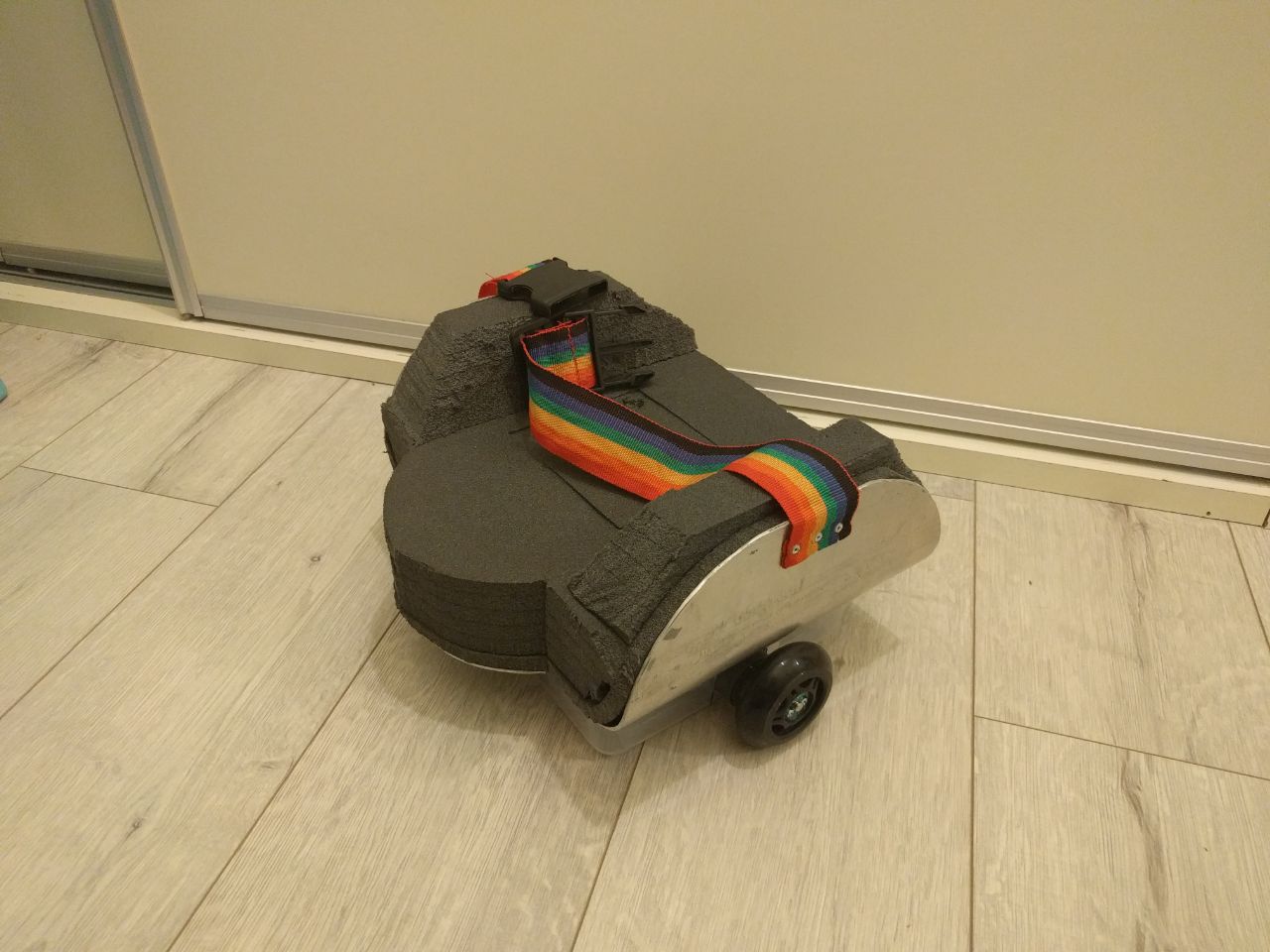
After testing with the child, we realized we needed a strap to prevent him from flipping over on the platform:
To conclude this part, here are some photos of the final platform with everything attached:
The bottom view showing electronics under the transparent case: the battery on the lower part, the motors in the middle part, and the Arduino and drivers on the upper part. Two rubber pads are positioned on top of the case, in place of the two problematic wheels.
The top view: The foam, with a removable square in the middle to enable access to the switch and charging connector.
Gem sensors
To be honest, if I hadn't heard about the Gem sensors and their inventors prior to commencing this project, I'd have considered it way too complicated and probably wouldn't have taken it on.
The Gem, by Gemsense is a very cool product mainly aimed for use as a controller in the virtual reality (VR) revolution.
As it's intended for use as a controller, it has the following characteristics:
- It supplies real-time highly accurate data about its own orientation, at about 50Hz.
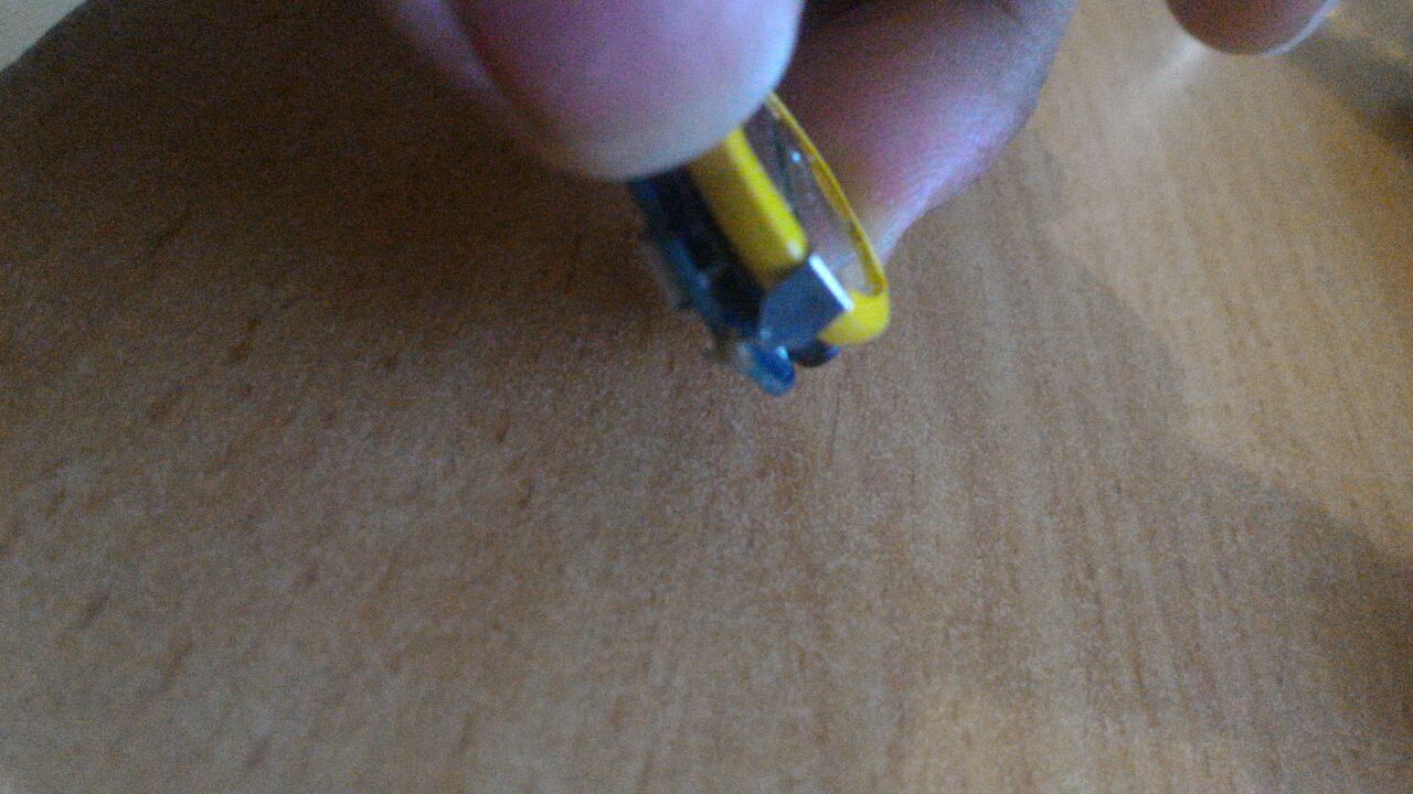
- It's very small - the size of a Lithium-Ion coin cell and is powered by one.
- It's low powered - can last for days on a single charge.
- It is supplied with a simple SDK and relies on Bluetooth low power (BLE) technology - which is relatively easy to integrate into designs.
All these characteristics are perfect for a VR controller, but also for our project - as they enable precise tracking of arm movement.
The Gemsense team delivered the sensors the day we ordered them, and provided enthusiastic support whenever we needed help. At one point, we even wanted to extend the Gems' transmission range, and with their help, we soldered out the internal antenna and replaced it with a ~3cm wire, as an external antenna.
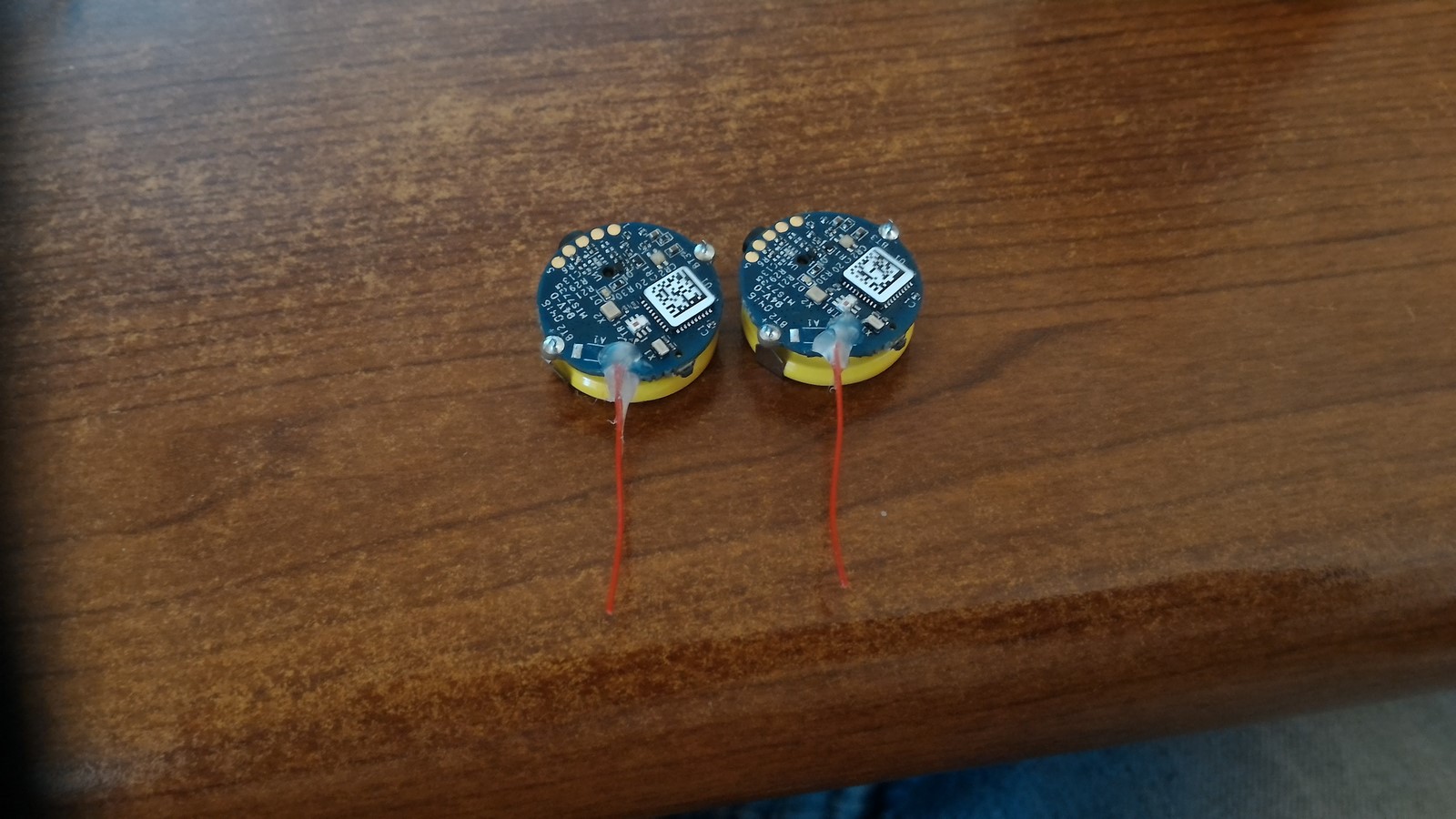
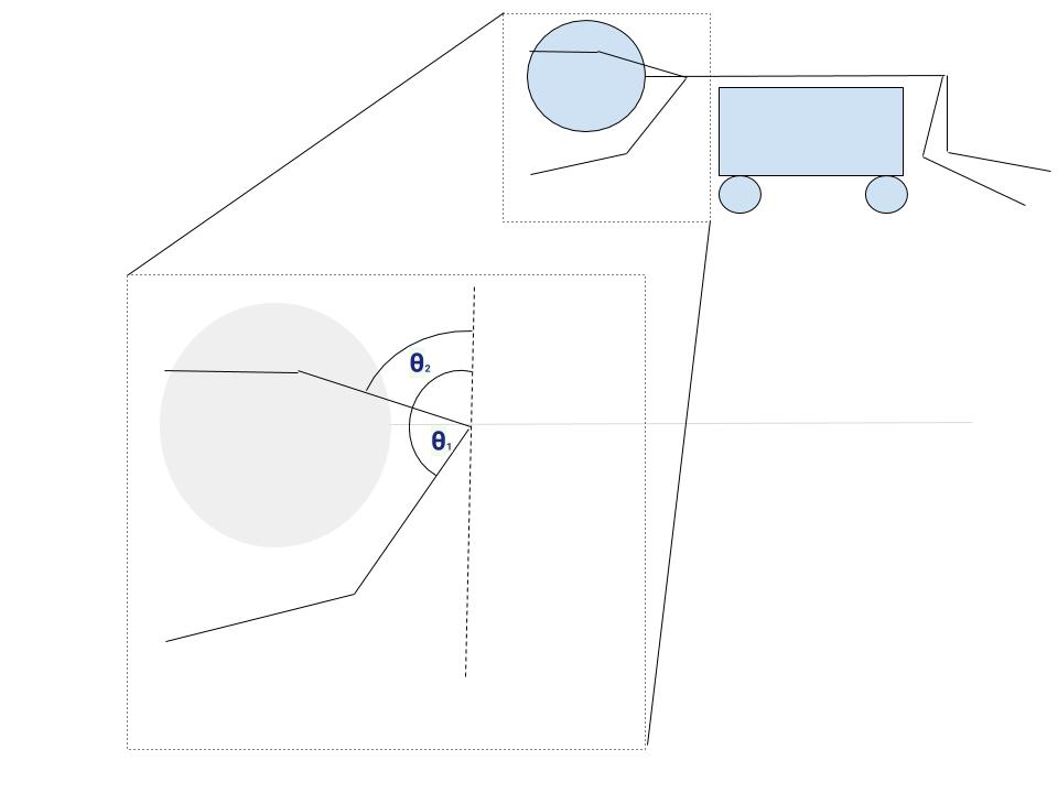
The Gem sensors supply the orientation data as quaternions, which is a mathematical way to represent space orientation and movement. Those working in this field are more acquainted with the terms pitch, roll and yaw (Euler angles) to express the orientation of a body in space. There's an injective function to transform a quaternion to Euler angles and vice-versa, so it didn't matter which way we chose to represent our orientation. However, when we wanted to perform certain transformations on Euler angles, we encountered problems such as gimbal lock. With a quaternion expression we would not have this problem. On the other hand, quaternions are less intuitive and needed strong mathematical understanding.
At the beginning, after reading the Gems' data, we transformed the quaternions to Euler angles, and then continued handling the data. However, after several computational errors, we decided that the safe thing to do would be to stay with quaternions. We studied the subject, then moved over to working with these expressions. From the quaternions we could extract the child's arm elevation - which is sketched in this very poor sketch:
In this video you can see an example of graphs showing a time series of the elevation angle, which changes with sensor movement.
Notice in this video that the two sensors do not behave the same way, even though they're on the same arm. We solved this problem later on.
Also note the 3D printed cases for the Gem sensors, supplied by the Gemsense team. These cases can be connected to a band like a watch, then around the child's arm - as seen in previous photos.
Python Code
This is the software part of the project. The entire code can be found here. In short, the file gem.py, the main code, is a multi-threaded code, where the different threads are used for:
- Sensor handling thread:
- Connecting to the sensors.
- Listening to the sensors.
- Collecting data from the sensors.
- Handling data, checking its validity and converting it into the arm elevation angle value.
- Pushing the data to the database.
- Recording the sensors' data to files - every sensor to a different file.
- Main code thread:
- Connecting to the Arduino serial through the USB COM.
- Handling the sensors' database - checking its boundaries, selecting the needed elevation vs. time series buffer.
- Analyzing the elevation vs. time tracking, and looking for positive pre-defined patterns.
- In case of a positive detection - sending a "move forward" command to the Arduino.
- Every 10 seconds - sending a "keep alive" command to the Arduino - resulting in a short blink of the LEDs.
- Recording all serial events to a file.
- When we start the code, start recording using the computer's webcam. (This part was coded but never used, and eventually was done manually).
- Analysis code thread (wasn't obligatory for the actual work, just for debugging):
- Drawing graphs using the current database found in the memory.
In general, we tried to have as little code as possible on the platform and most in Python on the computer. This was much easier than having to open the platform casing, connect the Arduino and flash a new program. Eventually the Arduino would get all needed data through wireless communication. The data consisted of five Bytes, which stated the platform ID, the direction to which each motor should turn, and the power to be supplied to each motor. The only parameters fixed on the Arduino were those taken for safety, such as the time to stop the platform and such.
I'll try to explain here a bit more about the code functions, should someone want to use it:
Handling the Gem sensors, defining their callbacks:
    gemMgr = GemManager()

    gems[0] = gemMgr.Gems.values()[0]
    res = gems[0].setCallbacks(onStatusUpdate,onCombinedData)
    gems[0].connect()

    if len(gemMgr.Gems) > 1:
        gems[1] = gemMgr.Gems.values()[1]
        gems[1].setCallbacks(onStatusUpdate2,onCombinedData2)
        gems[1].connect()
def onStatusUpdate(st): - Handle Gem if is disconnected.
def onCombinedData(quaternions,acceleration): - Handle Gem data if it is received.
def get_elevation(quat) - Function that receives quaternion values and outputs elevation angle value.
def CheckElevation(vec): - Function that receives a pre-defined number of elevation measurements and outputs a number that states if the arm hasn't moved, if it has just moved up, or if it has just moved down.
Here's an example of one of the "if" cases that results in a serial signal to the Arduino to move the platform. In this example, we discovered that one hand was just lowered, while the other hand didn't move, and was on the floor:
        if hands_trend[0] == HAND_DOWN and hands_trend[1] == HAND_UNKWON and dup_gem2_vec[dup_gem2_counter-1] > HAND_ON_FLOOR:
            if last_case != 1:
                print >> events_fd,time.time(), 'CASE 1 ::: hand 1 down,hand 2 on the floor'
                events_fd.flush()
                platform_controller.move_forward()
            last_case = 1
def figure_thread_loop(): - Plotting the data
Testing
Naturally we had to test each of the parts of the project individually, then the whole system together. We wanted it to be useful from the outset, and not spend too much time refining details and losing valuable time. To do so we had taken the next measures:
- Electronics and mechanics - we tested the platform electronics, motors, with the relevant weight.
- Software - ran many scenarios and tried to convert almost all numerical values into global parameters so they could be adjusted easily on the first real run with the child.
- Gem sensors - functionality, accessibility and comfort - one team member had his two-year-old daughter wear the sensors and test them. He recorded a video and sent it to us with logs - which we analyzed to understand expected values and optimize parameters. The team member approved this video for publication, so here's a short part:
- Entire system - to test the entire system - well, the first time I decided to try it on myself. In this short video we are testing the "one hand on the floor, one hand rising" case:
Conclusion
If you got this far, there's a chance you found this project interesting and want to contribute. If so, let us know. If something in the process wasn't clear and raised questions, please let me know and I'll try to clarify.
All the code can be found here, and in particular:
- ComputerArduinoCode - Code for the Arduino connected to the computer.
- ComputerGemAndPythonCode - Code for handling the Gems data, analyzing it and controlling the platform.
- PlatformArduinoCode - Code for Arduino on the platform.
- ProcessingCarControl - Manual code to test the communication to the platform and its motors.
Contact information:
- Here - Through the comment section.
- Facebook - Our page.
- Email - whatimadetodayblog at gmail.