The last post I wrote about some festival el-wire product reminded me a big project which I've done to the same festival last year. Unfortunately, I didn't document my work so much back then, and I also can't find the code, but still have some videos, photos and my own memory, and the code was pretty simple, so lets see how it goes.
The project in a few bullets:
- Bicycle on a stand, where the back wheel connected to an alternator which produces energy when the bicycles are in use. The energy is being used for:
- Charging a lead acid 12V battery.
- Lighting a massive (~300) WS2812 RGB led strip.
- Charging your phone.
- Turning on a fan in the front.
- Activate an Arduino and 4-digit 7-segment in the front which shows a timer and your speed.
- Extra feature: On the back wheel there was also another Arduino with 4 RGB strips which change their color according to the wheel speed
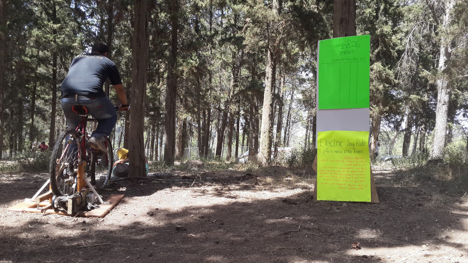
This is pretty much how it looked like in the festival:
The final result was very nice but was actually very different from the original planning. Due to our lack of experience and time we had to pivot to another idea. It wouldn't be much of documentation if I won't tell about the entire process.
The Original Idea
About six weeks before the festival we decided to contact the festival organizers and suggest them some projects we would like to build. We did it mostly to determine a dead-line for the project so we wouldn't drag on with it. We suggested two projects, and both of them were happily accepted by the organizers. The first one was a solar-powered phone charging station which I have already written about. The second project was a bicycle wheel with RGB led strip on it, which present a low-resolution photo when the wheel turns fast. The idea sounds pretty simple because the tons of POV projects which exist around the web. It seemed so simple that we thought it might not be challanging enough and had some more ideas such as uploading the photo from a smartphone via Bluetooth and charging the battery which powers the leds with the energy coming from the turning wheel.
I started by ordering from Ebay some addressable RGB led strips, WS2812 and LPD8806. I paid extra to get them fast but as I should have expected, our postal company is pretty shitty and it didn't happen - and that's pretty much the main reason we didn't go with the original plan. The leds arrived a week before the festival and the only thing we had time to do is activate them as they are.
But anyways, during the time I waited for the shipment, I start making some tests. In order to detect the speed of the wheel I decided to use what I had in my house - A reed switch sensor which is commonly used for alarms. I was wondering how precise it can detect a wheel turn. So the first circuit I've built was according to this sketch:
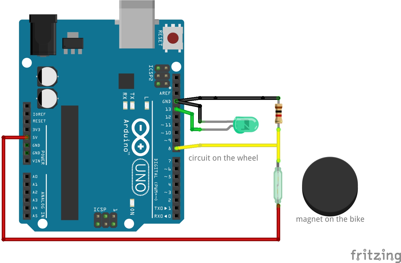
That was just a simple circuit to test the reed switch. It worked pretty good! The code I wrote turned on and off the green led everytime an interrupt was received by the reed switch moving next to the magnet. Notice the green led on the next video:
Just make sure to connect the Arduino pretty good to the wheel. The first time I did this test I turned the wheel really fast, the Arduino moved a bit and smashed into the bicycle shield :(.
Next - I took my old project of a led strip controlled by an Arduino and a microphone and connected it to the wheel, without the reed switch.
Here I found out something interesting. Notice on the video that the default PWM rate of the Arduino is about 1000Hz and it could actually be seen as a square wave when turning the wheel (leds goes on and off). I realize at that point that later in this project I'll have to handle with this problem. The WS2812 led strip work in a different way but still the refresh rate need to be fast enough. First I tried to compute what would be a good refresh rate for the led strip.
So - Lets say a person is cycling at speed of $V$ meters per second. The furthest part from the center of the wheel with radius $R$ will pass $2 \pi R$ every complete wheel turn. The overall time it takes to make one wheel turn would be
$$
T = \frac{2\pi R}{V}
$$
Lets say we want to refresh the leds at least every $\theta$ radians, then the minimal time $dt$ for refreshing:
$$
dt = \frac{T \cdot \theta}{2\pi}
$$
The minimal distance the led will move while turning is roughly $dx = R\cdot\theta$.
Lets calculate an example: Suppose the bicycle drive very fast at 36 KPH, which is about 10 m/s. And suppose the wheel radius is 0.3 m and we want to refresh the leds every 0.5 degree, which is about 2.5 mm of movement at the outer part of the wheel. The $dt$ between two commands is about 260 microseconds, which is around 4000 Hz refresh rate.
If I was about using PWM signal from the Arduino the solution was pretty simple. Using the examples on this website, the arduino registers can be changed on setup and the PWM rate can be changed to much greater values (up to 62.5 KHz).
With the WS2812 led strip however, it is a bit different. According to its datasheet it supports 800 Khz of data. Checking it more precisely, 1 bit of information takes around 1.25 microseconds, which means 10 RGB leds, each need 24 bits of RGB color each, will take 300 microseconds which wasn't such a great refresh rate. Moreover, the datasheet states that 1 bit of information takes 1.25 microseconds +/- 600 nanoseconds, which is a big different if you need high precision. I realize I will probably not use the WS2812 I ordered, but according to the LPD8806 datasheet it seemed to be faster and more stable for my purposes, supposed to get to 4KHz with a few dozens leds.
Well, lets forget all the math and worries and continue focus in the fun I had that time :D. I continued with the PWM driven led strip, changed the PWM rate to a higher frequency, changed the led strip to a full RGB led strip and made some more examinations:
Next, I connected the reed switch and modify the code such that only when the speed is above a certain value the rest of the program will start (Don't remember what was the value, around 3-4 turns per second).
Finally, I realized the festival coming soon, I haven't got my led strips yet and won't have time for both learning how to use them and writing the code for the POV project. So I decided to stay with the fact that a wheel making colors is nice enough (together with the rest of the project I will describe next), just made a last small modification and put the strips slightly biased from one another to create the feeling of a full colored wheel when turned fast (In the video it doesn't seem like it but it was, you have to believe me!)
In general, this particular project failed, but when I think about it a year later it was actually a great success. I learned a lot while failing, and by pivoting part of the idea we actually made a different project which was still very impressive.
The Pivot
And now for something completely different. While me and my friends were thinking about the original idea, we wanted the bicycle to have a nice stand and the ability to produce electricity while using it. It was pretty obvious that we will have to copy the work of a dynamo and we start looking for a big DC motor that will be connected to the back wheel of the bicycle. Unfortunately, big DC motors as we were looking were pretty expensive and hard to find around my area (purchasing from abroad was out of the question because of the shipment issues), but then another friend who works in a garage offered that we use a car alternator instead, and even gave as one for free!. I must admit that until that day I never knew how an alternator works but that gave me the push to learn about it.
How does a car alternator work? There's tons of YouTube videos with animations and such that can explain it much better than I can write here, but I'll still gonna give some general explanation. A DC motor usually consists of magnets and a coil. By moving the coil around the magnets or the other way around, we will create AC current flowing through the coil. With an alternator it is a bit different. Alternator has two sets of coils, inner and outer. When we connect the inner coil to the battery (This is what you do when you switch the power on in your car) some DC current start flowing through it, creating a magnetic field, much greater than if we've used magnets. When we start turning the alternator (start the engine in your car) the inner coil's magnetic field turns and creates great values of AC current in the outer current. Car alternator also have a rectifier which change the AC current to DC current at a voltage of around 14V, which is perfect to charge a lead acid 12V battery, surprisingly the same battery as you have in your car. In Conclusion, it seems the alternator can produce a lot of energy but its disadvantage is the fact it needed to be fed with some initial current in order to work, which means that if a car is powered on but the engine is off it will slowly drain the battery.
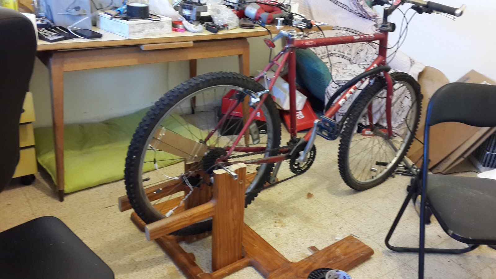
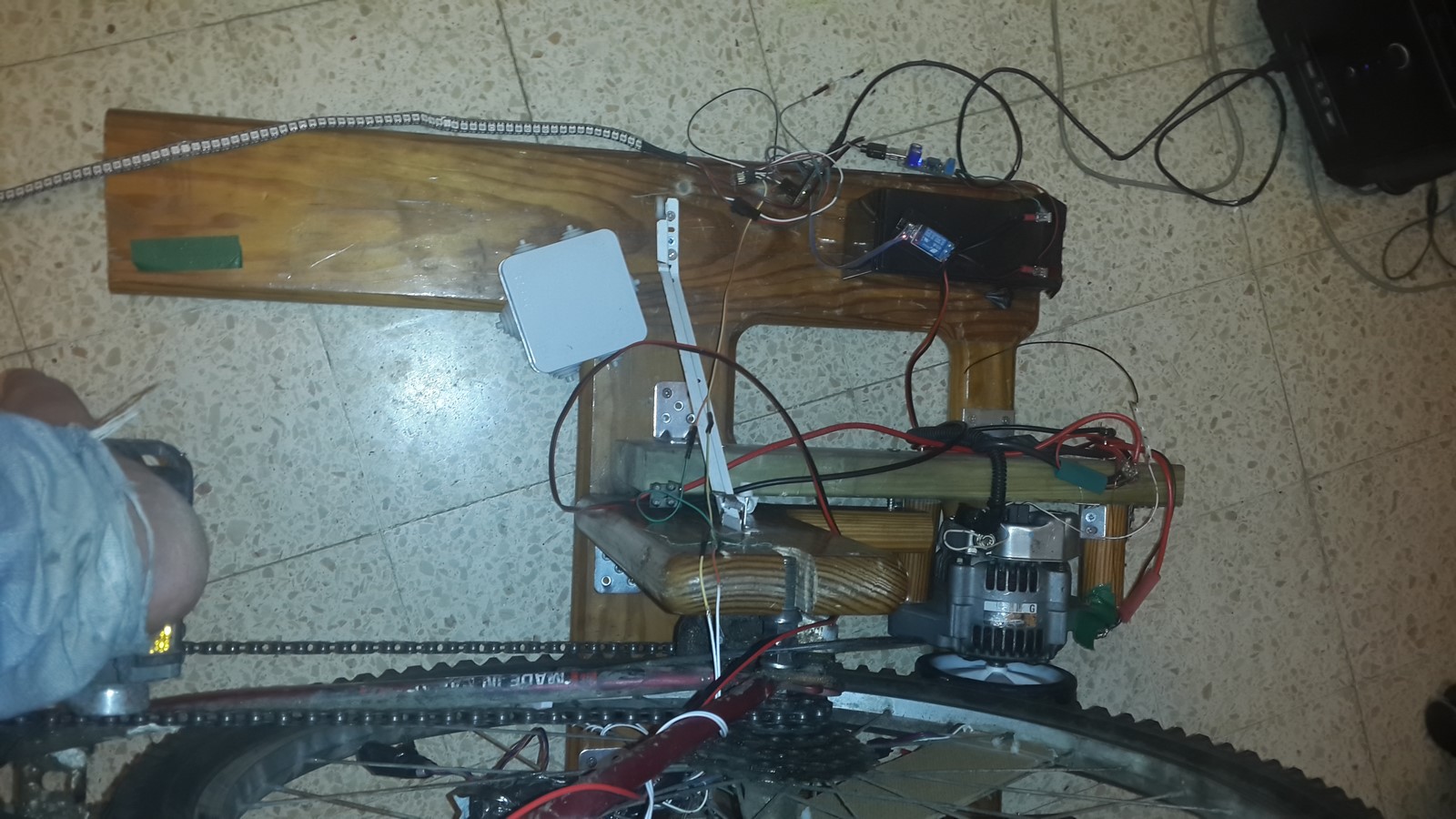
Back to our project, we start by building a pretty shitty stand for bicycle, made of a wooden bed we found outside.
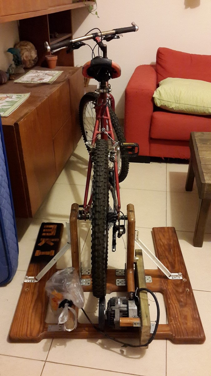
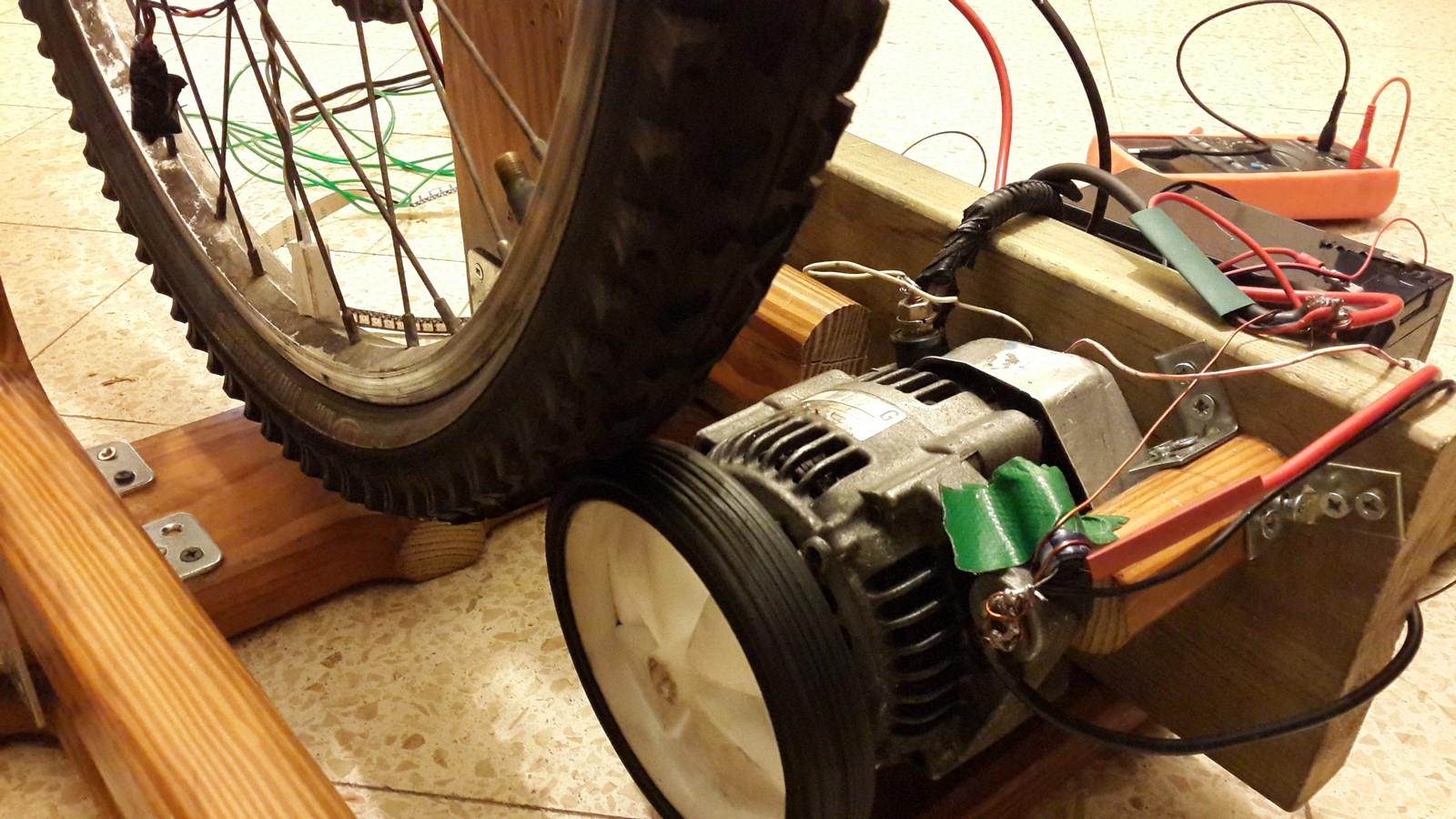
Later, with the help of our friend from the garage we added some metal bars to support the wooden stand and fixed the alternator at the bottom of the back wheel. In order to connect between the wheel and the alternator we've used a kids training wheel which was put on the alternator and the small friction between the wheels made them turn each other. It turned out to be a much simpler solution than using chains and such.
Next we connected the alternator to the battery. Both the inner and the outer coils.
Now the measuring has begun. While not turning the wheel, some current was flowing from the battery through the alternator, draining the battery slowly and the measured voltage was 12V. When starting to turn the bicycle wheel, nothing really happened. After turning the wheel at a certain speed two things have happened: It became much more difficult to turn the bicycle wheel and great amount of current start flowing from the alternator to the battery, with a measured voltage of 14-14.5V. Great success so far!
The only problem was the fact that we planned to bring this project to a festival, and leaving it for several hours without anyone using it would have drained the battery. This is where our Arduino friend comes for help. We've created the circuit as in the next sketch. The sketch might not be entirely correct, I've sketched it from what I remembered after a year :(
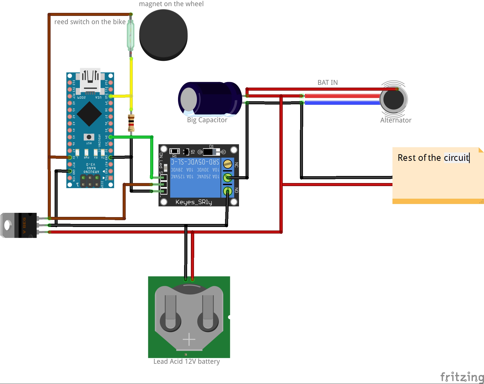
With the right code the circuit will do several things:
- While no one is using the bicycle, the battery powers only the Arduino, which draws very low amount of current.
- When the wheel start to turn, the Arduino detects it using the reed switch on the bicycle body and the magnet on the wheel. If a certain wheel speed is detected, the speed needed to activate the alternator, the Arduino opens the relay.
- While the relay is open the battery charges the capacitor to 12V which holds the voltage of the inner coil and the outer coil start to produce a higher voltage, charging the battery and powering the rest of the circuit.
- After a few seconds the battery can be disconnected from the circuit (by closing the relay) and the rest of the circuit can be still powered by the alternator - Thus proving it can be powered only by the great power of cycling!!!
Note that the capacitor has to be of a big value and has an important role. At the beginning we didn't use the capacitor and every time the alternator started to work and stopped immediately when closing the relay. Only after adding the capacitor we got it working such that when the alternator worked and the relay was closed the capacitor acted like another small battery which kept feeding current to the inner coil.
The Last Three Days
A few weeks have passed, and there were only three more days to the festival. I've finally got the led strips a few days before and the alternator finally worked. Since we decided to desert the "picture on wheel" idea and focus on the energy reproduction we were on the right track. We've connected the led strip to the circuit powered by the alternator and tested it for the first time.
We were very satisfied with the results. A WS2812 led strip of almost 300 leds draws about 11 Amps max (~55 Watts) and the alternator had no problem producing this amount of energy. Next, we connected at the front of the bicycle a fan and a smartphone charging stand which can be seen in the next video:
In that video, I wrote a code where the leds on the strip will turn on according to the speed of the wheel. Afterward we decided to make some kind of gamification out of the leds strip and make them turn on one by one as long as the person keep cycling, and the leds color will be determined by the wheel speed (This can be seen on the first video of this post).
You might have noticed the smartphone clock on the video - the time was almost midnight on the day before the festival and everything worked but looked really messy:
At the rest of the night we made everything more robust, and my girlfriend made us a nice poster for the festival. The lights on the wheel (From the first paragraph of this post) stayed there and also contributed to the beauty of the project.
People of all ages really enjoyed testing this project and I hope you enjoyed reading - I wrote this documentation mostly because it has been so long since I made this project and didn't want to forget it. Still I found it hard to remember some parts I've already disassembled - Hopefully I'll build it again and write some more details at some point.
AA