EDIT 4/4/2016: Check out part 2 of this post. It is mostly about a software update I've done. The code is much better, the control is much simpler and the display is much nicer!
EDIT 26/3/2015: This post is updated frequently due to the project process, you might see some "edit" notes on the way. Oh and I got some GREAT NEWS! We finally found time to put down our power tools and opened a Facebook page! "Like" us to follow new posts and projects - we promise not to spam :)
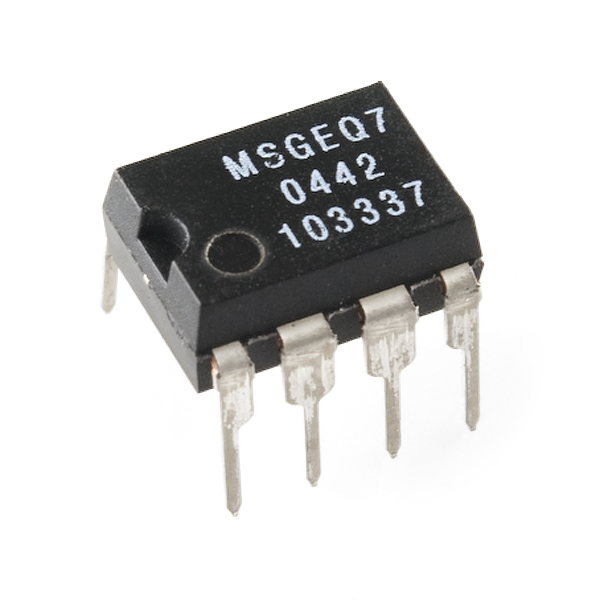
Two weeks ago I got my ESP8266 Version 12, which is a new version of the ESP8266 micro-controller with more GPIOs, so it seems some nice things can be done with it. If you haven't heard of the ESP8266 check this older post from the blog. Also, I got the MSGEQ7 chip, which is a chip that outputs an analog equalizer from a sound signal. I was looking for a fun project to do with those two items, one which can help me also to learn LUA script, the language that is used to program the ESP8266. Finally, I've created this project: An equalizer display controlled by ESP8266 with the NodeMCU firmware, where the equalizer colors are controlled via WiFi. Check the video:
The project is not yet finished, but I've been learning a lot on the way and would like to share it here. Some more goals I want to achieve:
Arrange all parts on a PCB.DONE!Change LED strip into several strips making the visualization nicer.DONE!Upgrading the LUA code nicely into several header files and a main file.DONE!Create a nicer web platform to control the colors.DONE!- Send the sound signal via WiFi. (At the moment not sure it is possible)
The post will be divided into several steps which were crucial to make this project work:
- Flashing the ESP8266 V12 with a developers NodeMCU firmware. (EDIT: Recently, the official version has changed and the developers firmware is no longer needed. I left this instructions anyways for future use)
- Learning to use the MSGEQ7 using an arduino.
- Integrating the MSGEQ7 with the ESP8266.
- Bulding the display.
The ingredients:
- ESP8266 V12
- LM1117 voltage controller
- TTL / FTDI / Arduino / Any device with USB-to-serial module
- MSGEQ7 chip
- WS2812 led strip
- 3.5mm Aux Connectore
- Ceramic Capacitors: 68nF, 33pF
- Electric Capcitors: 2x100nF, 1x100uF
- Resistors: 200KOhm, 2x15KOhm, 2x220Ohm
- 20KOhm Potentiometer
- A few spoons of LUA code
For the display you'll need a picture frame, a mirror and a relective glass with the same size of the frame, and whatever comes to your mind to make it pretty.
Flashing the ESP8266 V12
First of all, meet the ESP8266 V12:
Just like the ESP8266 V01 it is a micro-controller with WiFi support, antenna on board and UART support. The difference is the amount of connections it got. The 16 Connections consist of UART, A/D, SPI, I2C, 11 GPIOs and more. This blog already has a guide on how to flash the ESP8266, however two things were a bit different this time:
- The ESP8266 version is different.
- The NodeMCU current official version (0.9.5) does not consist of a library to control the WS2812 so a developers version had to be flashed instead.
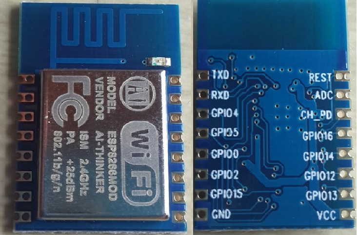
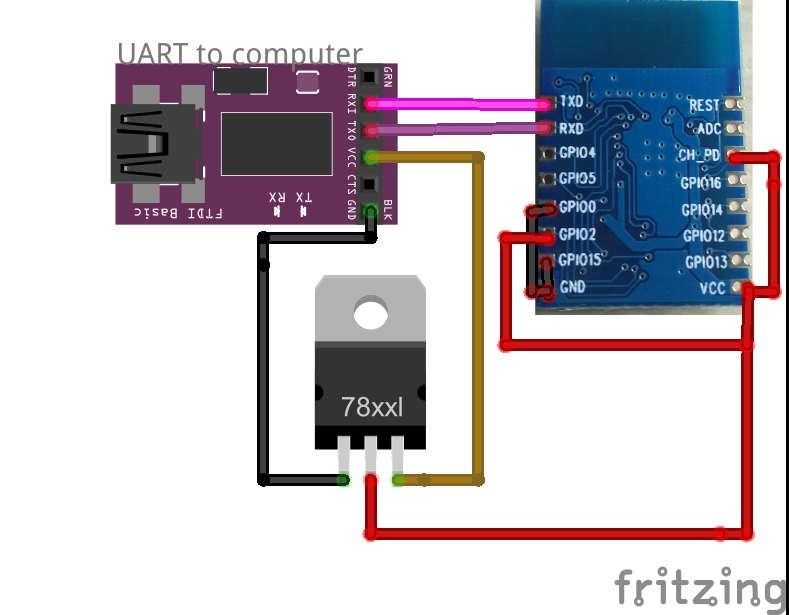
The first bullet is rather easy to handle. In order to make the ESP8266 V12 start in flashing mode the following circuit is needed:
- RX --> TX
- TX --> RX
- 3.3V VCC connection through a voltage regulator.
- Common ground
- CH_PD --> VCC
- GPIO0 --> GND
- GPIO15 --> GND
- GPIO2 --> VCC
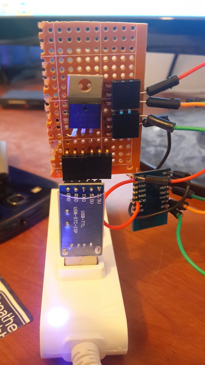
The last two bullets are the additions to the last post when using this version of the ESP8266. In order to save time in the future I've build a circuit for powering/flashing the ESP8266, which has the voltage regulator and connectors. I advice to do so if you plan to use this device frequently.While flashing I just add the GPIO2 and GPIO0 connection to the VCC and GND, and while working I disconnect the connectors.
On this project I am using a special library of the NodeMCU written by Markus Gritsch. Luckily he posted a link where you can download the firmware after he compiled it. In case the link doesn't work the bins can be downloaded from here.
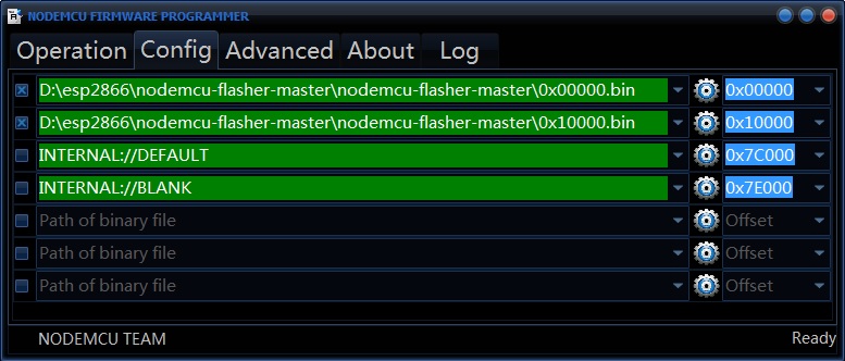
After you download the bins simply open the NodeMCU flasher (assuming you are a Windows user) and select the bins at the right addresses:
Then continue as before, selecting the right COM and flash. In order to check your firmware and later on write a code, I advice using ESPlorer which is a great tool for handling the ESP8266. It should look like that:
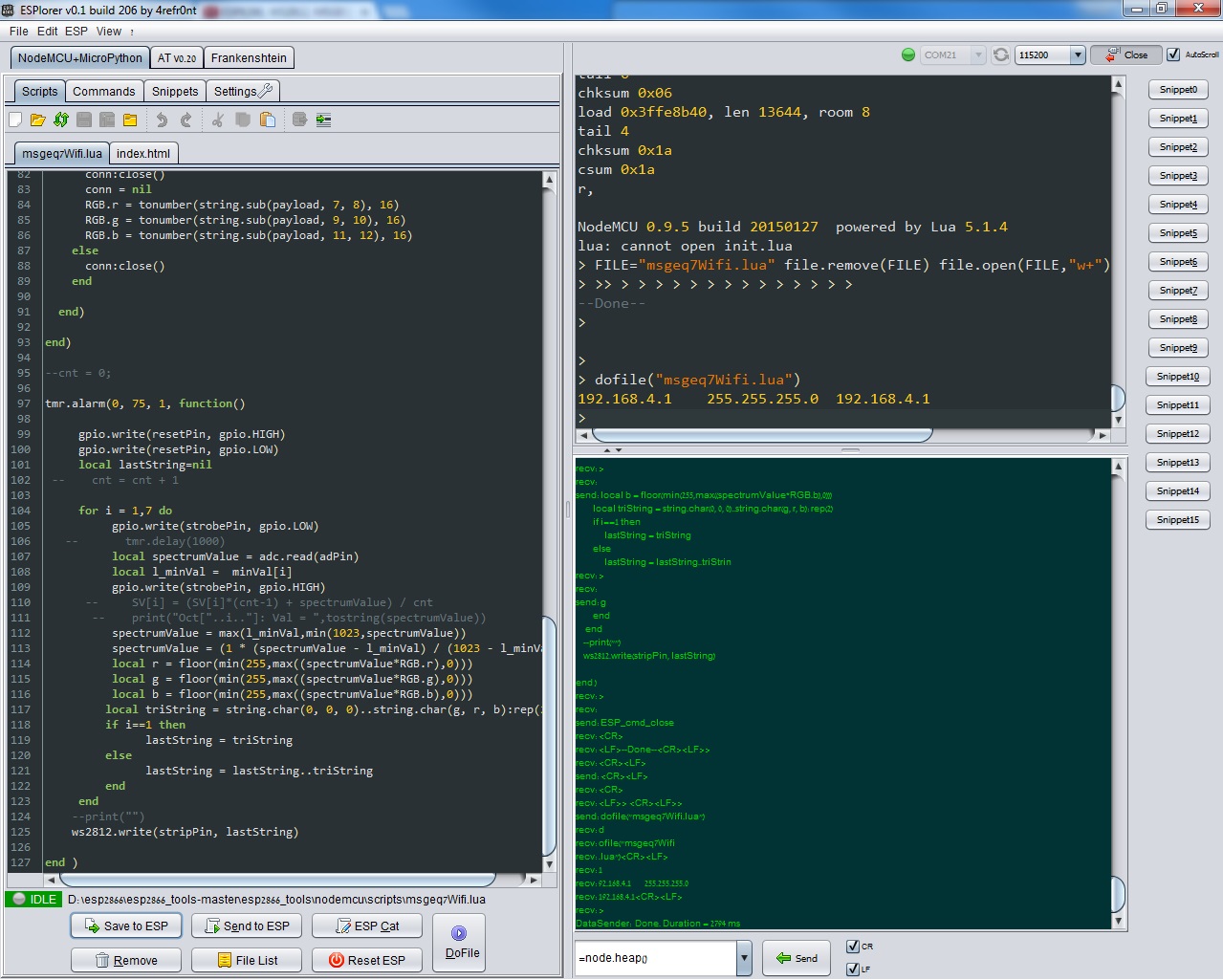
On the top-right you should select the COM and Baud Rate - Notice this firmware works at baud rate of 115200. After connecting you can write a LUA script and upload it to the ESP8266 - same as described in another post on this blog, just much easier. To test the WS2812 library use the next code:
stripPin = 2   -- Comment: GPIO5
g = 0
r = 255
b = 0
String = string.char(g, r, b)
ws2812.write(stripPin, String)
This code should light in red the first led in the strip assuming the strip connections are OK (The circuit is described later on this post). Following Markus Gritsch's link which I posted before, you can find also a full code which controls the leds via WiFi. This code can be tested as well to see the full system functioning. I've used the same code and modified it Later on for my project.
EDIT: I was notified by one of the comments [Jacob Gabriel], that the official NodeMCU version of the nodeMCU supports the WS2812 library. I tried it and it works great, the only change is that it recieves RGB string and not GRB string and the function has a slightly different name:
stripPin = 2   -- Comment: GPIO5
g = 0
r = 255
b = 0
String = string.char(r, g, b)
ws2812.writergb(stripPin, String)
If you are using the official firmware the baud rate should be set to 9600.
MSGEQ7
More than a year ago I have built a project, and also wrote a post, where an arduino gets a microphone signal as input and delivers the low, mid and high frequencies values. These values come out as PWM outputs and light an RGB led strip. While working on that project I had some hard time defining and applying digital filters using the arduino. It seems that the arduino was not fast enough to run a well-defined digital filter (FIR) and I had to choose between getting a delay in the outputs or compromise with a lower-quality filter. After a while I heard about the MSGEQ7 chip which basically does a similar thing but using analog filters on analog signals, which means no delay is expected. So how does it works? According to its data sheet this is the block diagram:
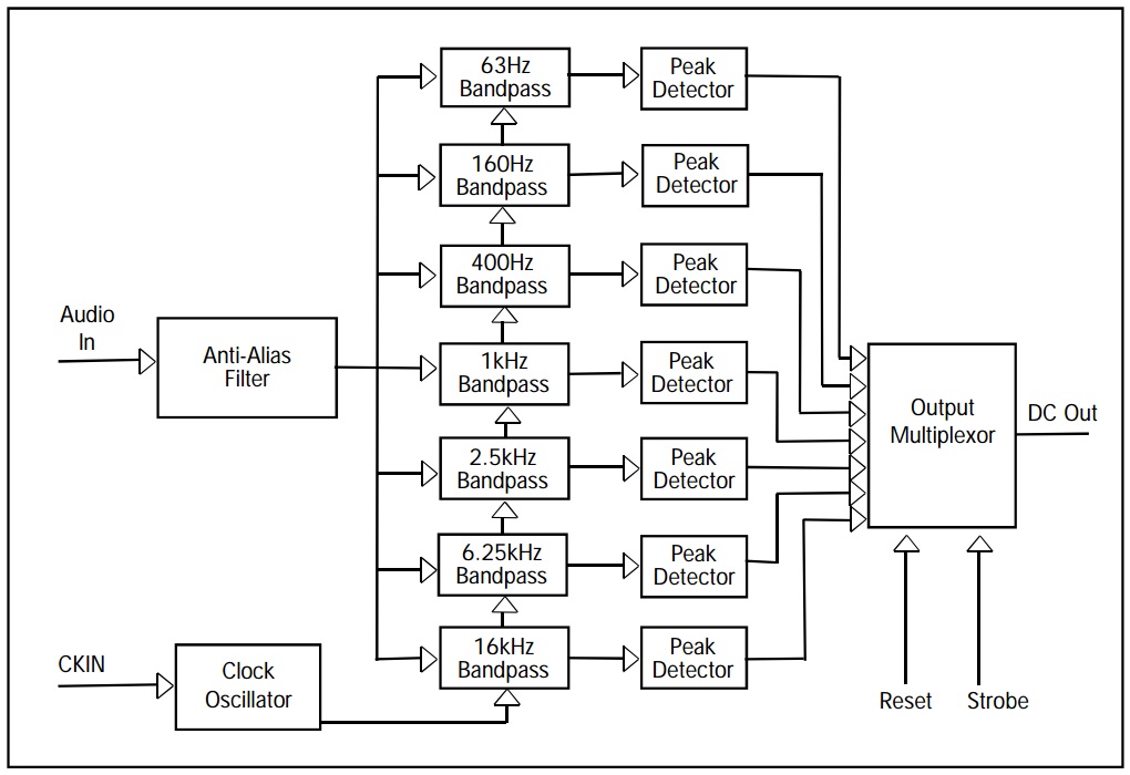
The audio signal goes through 7 band-pass filters and into a multiplexer. By using a strobe from the micro-controller we select which of the filtered-signal's values will be output from the chip. It is as simple as that.
As I am not so familiar with the ESP8266, I started by connecting the MSGEQ7 to an arduino following this instructable. I had to modify the code a bit since I was using the WS2812 leds. The overall circuit looks like that:
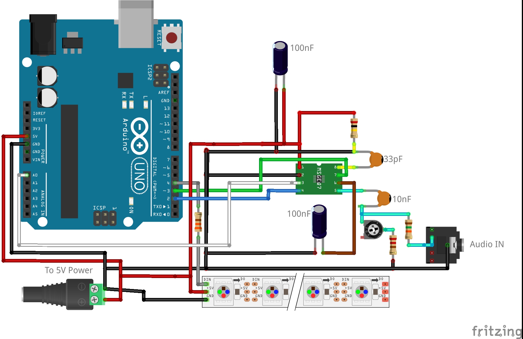
A few notes about the MSGEQ7 connections:
- Pin8 controls the clock oscillator which produce the band-pass filters, therefore it should have on its input the precise values of 200KOhm resistor and 33pF capacitor.
- Two more capacitors are connected between VCC and GND and from pin 6 to GND.
- The "audio in" plug usually has at least 3 pins: Left, Right and Ground. It is enough to connect only the ground and one of the channels.
- Pin 5 should get the audio signal. The MSGEQ7 amplifies the signal in 20dB (x100), so a good value of AC voltage at the entrance would be around 30-50mV, then the highest output values will be 3-5V. The potentiometer and a resistor connected to ground are exactly for that reason - Then you are not depended on the external music player volume. The 10nF capacitor should filter the DC offset. EDIT: Later, I found out a 68nF would do a better job.
- On the arduino: Pin2 - Strobe, Pin3 - Reset, Pin4 - Led Strip, A0 - Analog in.
My arduino code for this sketch can be found here. Notice those lines in the code:
    spectrumValue[i]=analogRead(analogPin);
    spectrumValue[i]=map(spectrumValue[i], filter,1023,0,255);
The arduino A/D sampling the signal in 10-bits of information but the output should be in terms of 8-bits. Moreover, the chip produces noise also when there's no signal at all, therefore values below the noise level should be nullified. These code lines make sure the 10-bit value will be over the noise level and mapped into an 8-bit value. The code was working as it should and now I was ready to continue to the integration.
MSGEQ7 + ESP8266
Up until now I learned how to write code to the ESP8266, and how to activate the MSGEQ7. Now it was time to integrate between them. I've built the next circuit:
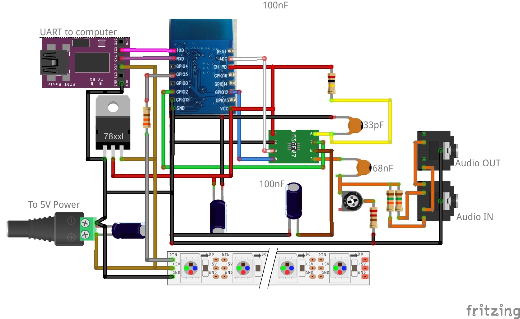
It looks like a complicated sketch with a lot of wires but it is mostly a combination of the two sketches I draw before. Nevertheless, some notes:
- I've added an output aux connector, and connect the two audio channels to the MSGEQ7 (not compulsory).
- The connections to the MSGEQ7 stays the same, but this time the VCC powering the chip is 3.3V, so all the places were connected to the 5V before are connected to 3.3V now (i.e the ESP8266 VCC).
- The ESP8266 gets its power through the voltage regulator as before.
- The WS2812 led strip still needs 5V so it get its power straight from the power jack. Also it needs another capacitor for protection.
- On the ESP8266: Pin15 still needs to be connected to the GND so the ESP8266 will function, as well as the CH_PD to VCC. GPIO0 and GPIO2 which were used before for flashing no longer need to be connected to GND and VCC.
- Other connections on the ESP8266: GPIO12 - Strobe, GPIO2 - Reset, GPIO5 - Led Strip, ADC - Analog in.
Unlike the arduino, the ESP8266 has only one analog in. A lucky guess would be that it is the only one functioning at the moment and future firmware will support more.
Since there were so much wires and a lot of room for mistakes I build this circuit on a bread board, not soldering anything yet. Eventually it was all connected correctly but looked like a mess - So if you do so be careful - It is very easy to make mistakes on the way.
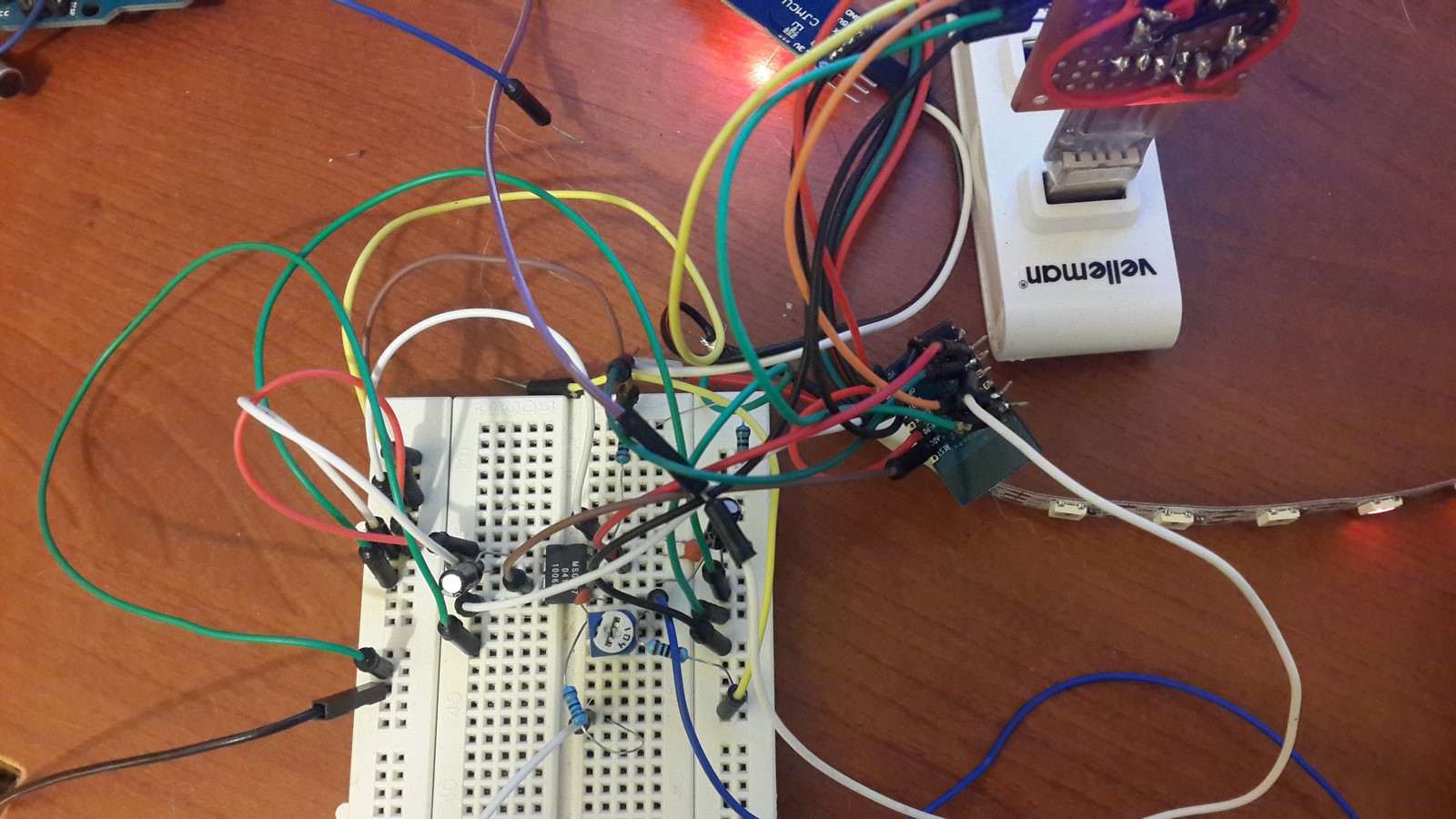
What cannot be seen on this image is the 3.5mm aux cable going from my computer and one going to the speakers. If you don't want to use two aux connectors you can use an aux splitter so you could both hear the music and check the graphic equalizer.
The next step was to re-write the arduino code in LUA script so it will run on the ESP8266, and also add a WiFi option to change the equalizer colors. The WiFi code is based on Markus Gritsch code. I made some modifications in the HTML file so it can send many more color commands than before, and on the LUA file so it'll receive and manage the data. Eventually the ESP8266 connects to your router using "info.txt" file which consists a string "SSID:PASSWORD" of your router and when you enter the ESP IP address you'll receive the next interactive web-page:
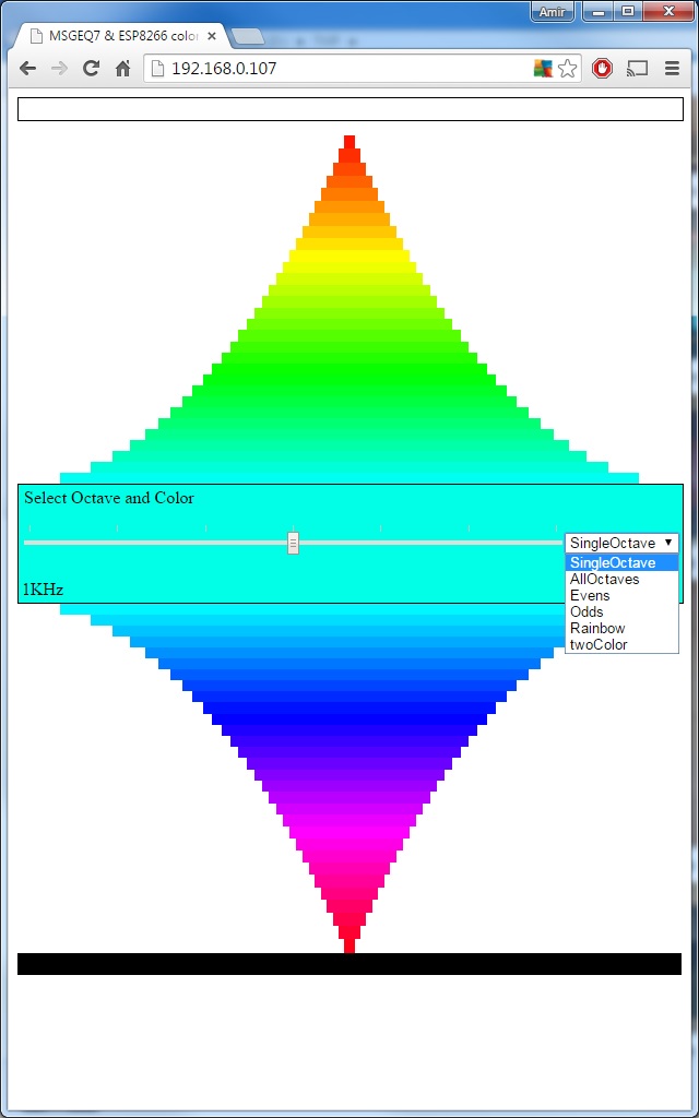
The page consists of many colors, when pressing one of them it will send a GET request to the server where the LUA script will receive the color value. It also supports the next commands:
- SingleOctave - Sending a single color value to a chosen octave band.
- AllOctave - Sending a single color value to all the octave bands.
- Evens - Sending a single color value to all the even octave bands.
- Odds - Sending a single color value to all the odd octave bands.
- Rainbow - Sending a command to start a sequence of changing all colors of the bands all the time.
- twoColor - Sending two colors of the lowest and highest bands and the rest will receive a linear combination of these colors.
By the way, it is very easy to change the ESP8266 mode to a hotspot mode so you don't need a router, SSID and password and can just connect directly to the ESP8266. The HTML code is written in "index.html" file and of course must be uploaded to the ESP8266 as well.
The full code can be found here. Here are a few important notes that I found out during the process:
General:
- The "Math" library does not exist on this firmware, so I had to write my own min()/max() functions.
- The GPIO map was a bit different than written here. Hopefully soon it will be solved. Basically all is the same except GPIO4 and GPIO5 which are the opposite than what is written. GPIO4 - pin1, GPIO5 - pin2.
MSGEQ7: The MSGEQ7 can be powered by 3.3V but the noise level is higher. With power of 5V it was about a value of 80 out of 1024 (10-bit). I've run a check script to average the noise level in each octave and found out the next values will be good for this project on its current form:
- 63Hz - 200 / 1024
- 160Hz - 150 / 1024
- 400Hz - 300 / 1024
- 1KHz - 300 / 1024
- 2.5KHz - 300 / 1024
- 6.25KHz - 250 / 1024
- 16KHz - 350 / 1024
It might be better just to use "350" in all octaves but I felt as the linearity of the filters was damaged when using 3.3V so eventually these values gave the best appearance. EDIT: I found out later on that the circuit powering the ESP8266 creates a noise which interfere with the MSGEQ7 (or maybe the A2D) and is the cause of most of this noise. By rubbing around the circuit some metal wires I managed to drop the noise level in all bands to around 200 / 1024.
WiFi: The WiFi handling is also very simple:
--These two lines create the hotspot:
wifi.setmode(wifi.STATION)
wifi.sta.config(SSID,PWD)

--Then, these two lines create a TCP server:
srv = net.createServer(net.TCP)
srv:listen(80, function(conn)

--This line is used to define what happens when someone send a GET request
conn:on("receive", function(conn, payload) [Code here] end`
Run-time issues:
- I've activated the reading-A2D-values-writing-to-WS2812 function every 75ms using the tmr.alarm() function and every 85ms when enabling the "Rainbow" mode. In order to use this function simply write
tmr.alarm(0, 75, 1, function() [Code here] end. If the tmr.alarm() needs to be activate again before it routine was finished, it will eventually stuck the ESP8266. Notice that the WiFi recieve function is also a cyclic funciton so it is best to stop the tmr.alarm() when the recieve function works and start it again when it is finished. Compiling the code can also help reducing these issues. - If you check my code you will notice I have two LUA files "Func.lua" and "main.lua". At the beginning all the code was in a single script but when trying to compile it the ESP8266 reset itself. The reason was that if a script running for too long, a time-out interrupt will reset the module. After dividing the code to two files I could compile both with no problems. By the way, using even more files which suppose to interact with each other in real-time also can cause the ESP8266 to reset due to memory handling problems.
- I've activated the reading-A2D-values-writing-to-WS2812 function every 75ms using the tmr.alarm() function and every 85ms when enabling the "Rainbow" mode. In order to use this function simply write
Memory handling: The heap size on the current NodeMCU firmware, is about 22Kb. If the program has a lot of variables and print() functions it will not run and you will get a "Not Enough Memory" error. Some ways to solve the problem:
- Use the NodeMCU "only integers" firmware.
- Use more local variables
- Don't use variables at all if they are not needed.
- LUA doesn't free your global variables so you can do it by yourself using
x = nilto free x variable. - Compile your script! It will increase drastically the memory management.
At this point the project was finally working, but I lost some hairs due to the whole run-time and memory issues. Even after doing all of the above I found out the most important conclusion of this project which is actually pretty obvious: LUA language is too high level and is not the right language to develop a real-time project. This firmware is great for all kind of IoT projects but a different firmware might be better for this kind of project.
After the project was working, I've arranged all the electronis on a PCB:
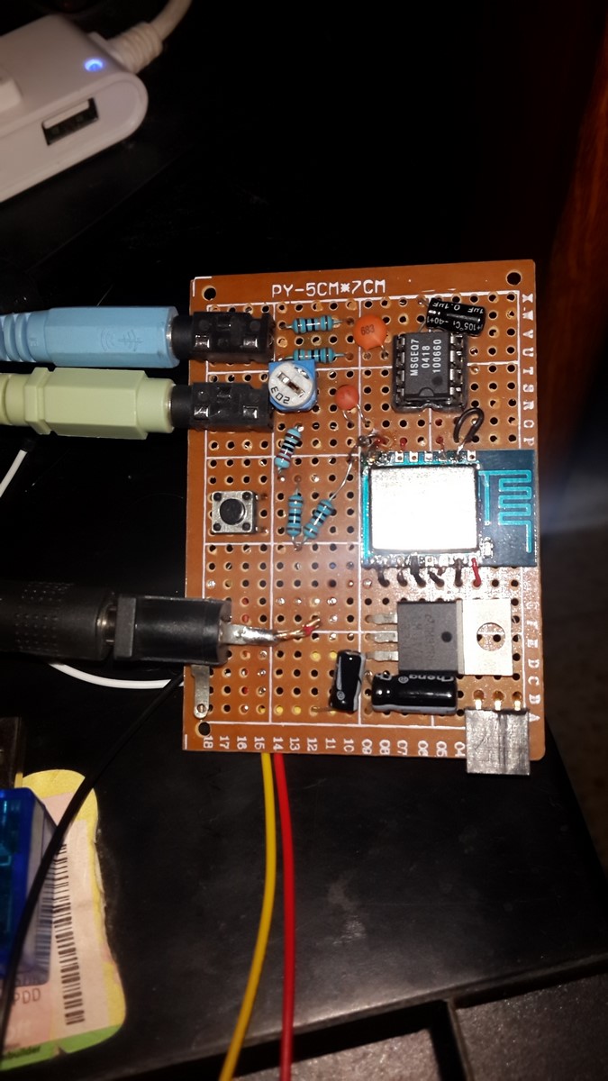
The PCB consist of:
- All the electronics according to the sketch.
- Audio in and out jacks.
- Power jack.
- 3 Pins for Ground,Tx,Rx to flash firmware or upload new files.
- Button (Not shown on the sketch), connecting GPIO0 and Ground. That way if the button is pressed when connecting the board to the computer the ESP8266 will be on flash mode.
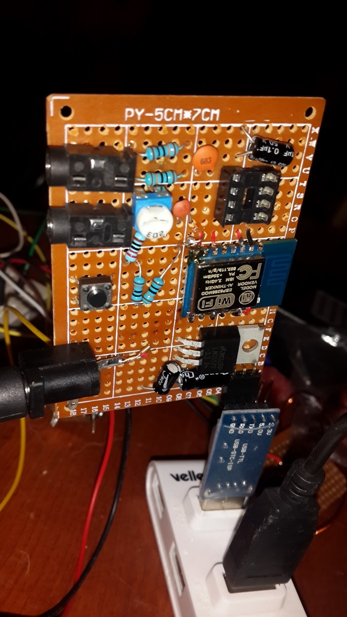
After the PCB was ready I've connected it to the computer, flashed the NodeMCU software and upload the code:
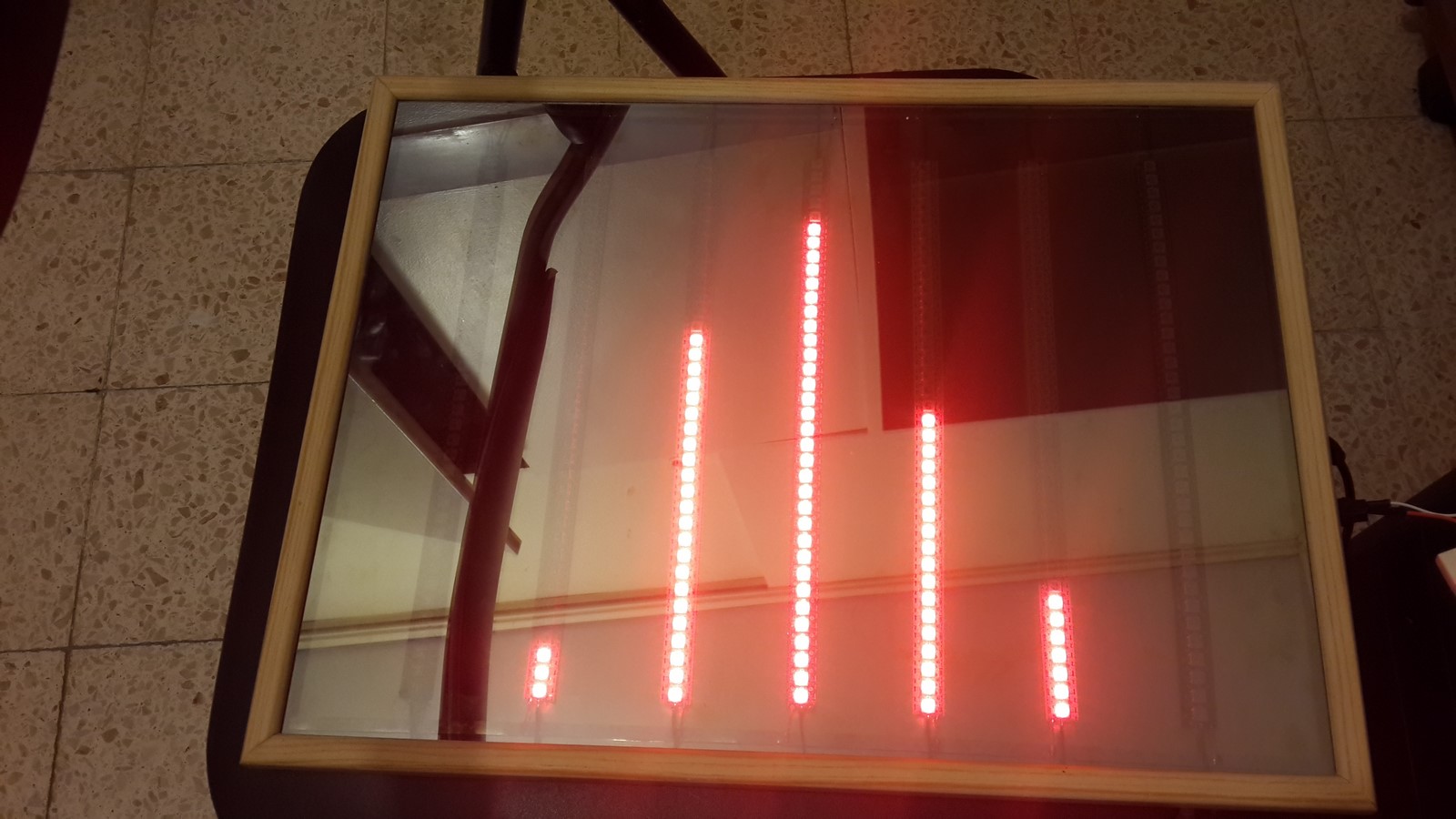
As explained above, I suggest making this projects step-by-step. At the beginning, the project was working only as a "proof-of-concept" with 30 leds:
later on I connected 2 meters of 144 led strips and checked no unexpected issues, beside all the issues I mentioned above :o, and then decided it was time to build a better display!
The Display - Lots of photos here :)
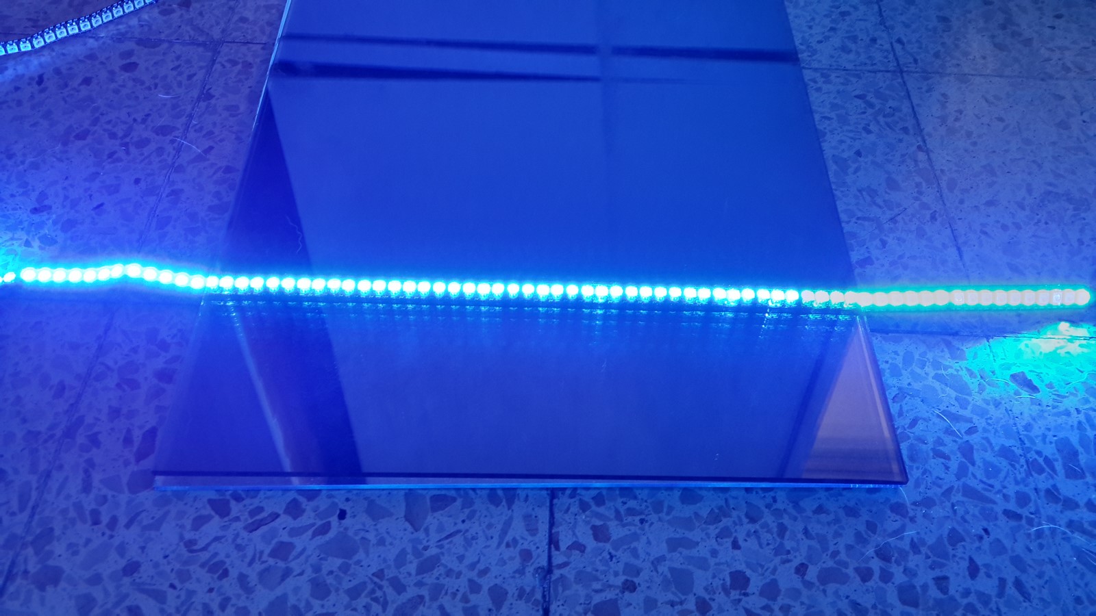
I decided to create a similar display to the one in my 3D Magical Led Picture post, only bigger and with some minor changes after learning a few things from back then. The idea is simple - Take a mirror, turn on a led strip, put on it a reflective glass and you will get the "infinity mirror"
However, if we face the strip up (as I wanted) the infinity illusion diminishes
:(
Then I remembered I recently found a non-working LCD monitor, tried to fix it, broke it even more and eventually disassembled it. Besides the lamp layer and the pixels layer, I was really surprised to find many layers of all kind of faders and reflectors inside
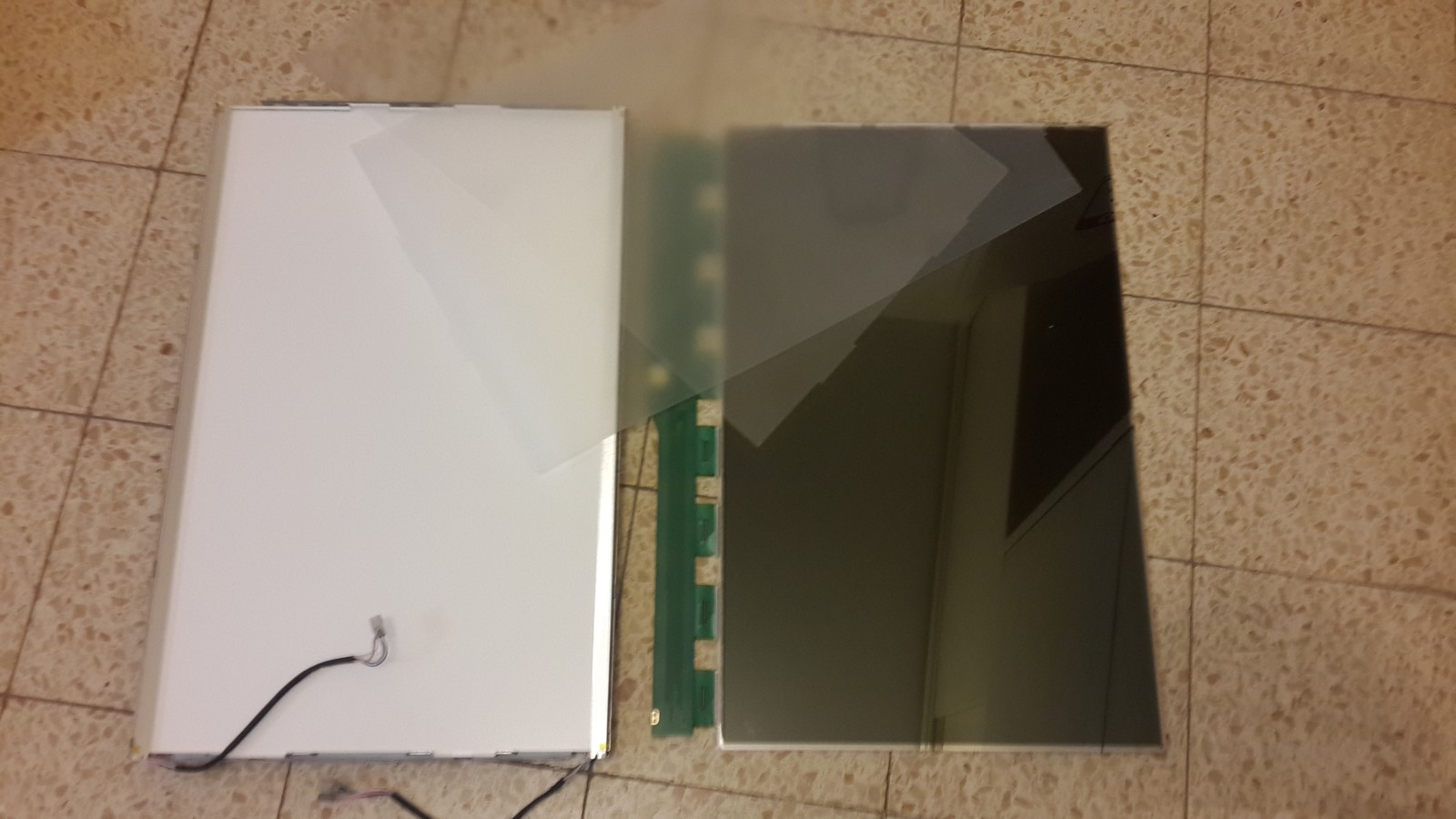
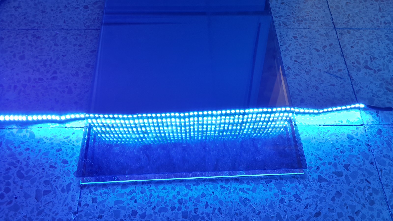
One of this layers gave a really cool appearance when placed a few milimeters above something (By the way, have you heard about the BMVA? ):

So I tried to test the layers on the led strip:
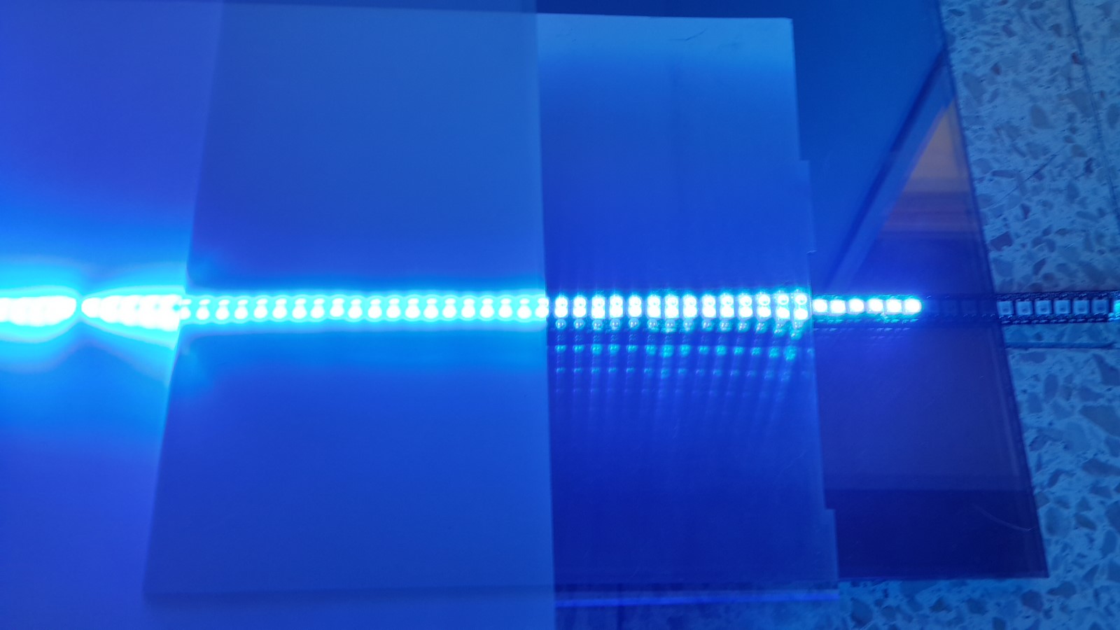
The right part of the photo is as before, the middle is with the new layer and the left with another layer. Notice that the middle part gave back the cool "infinity" effect.
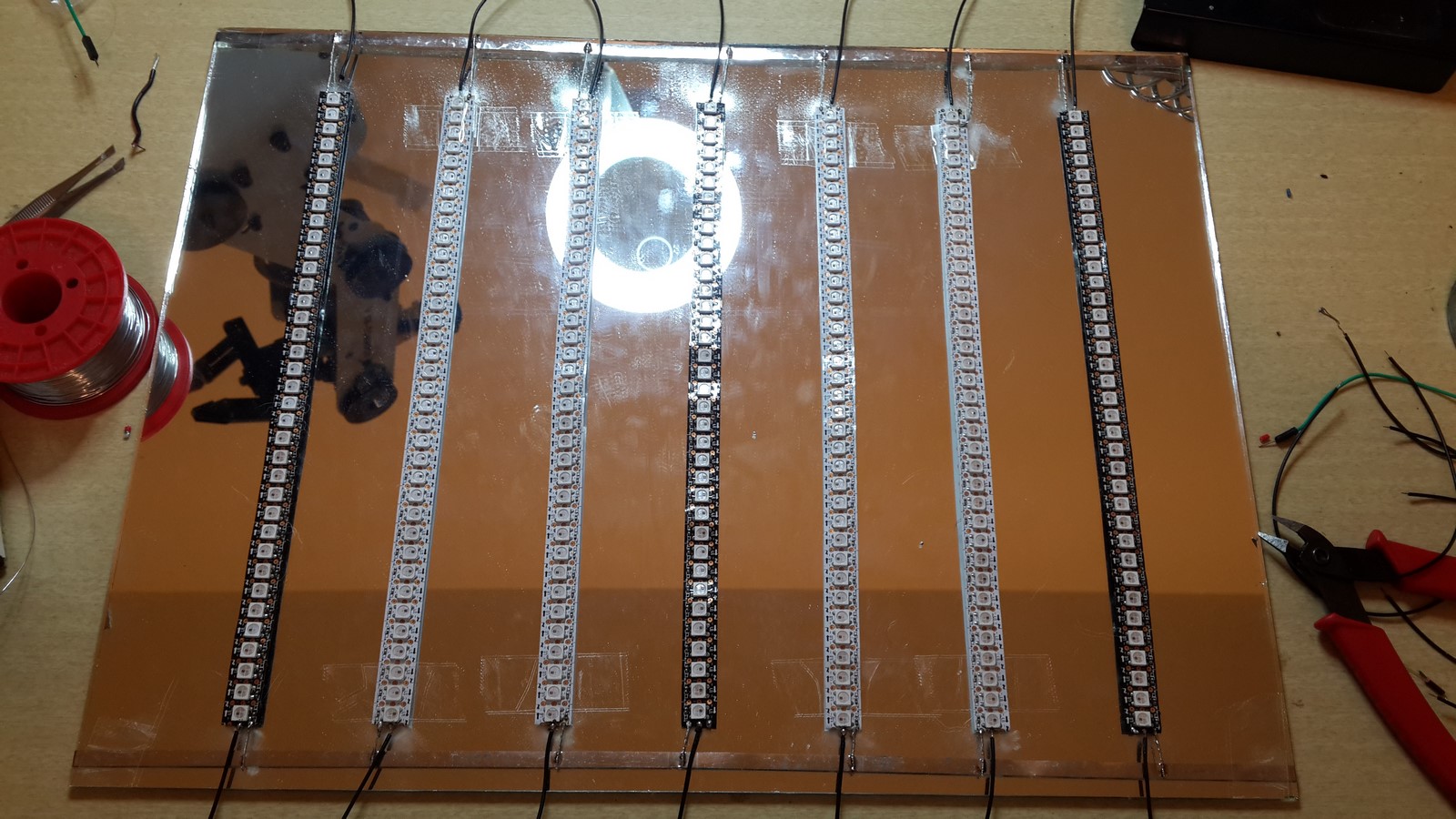
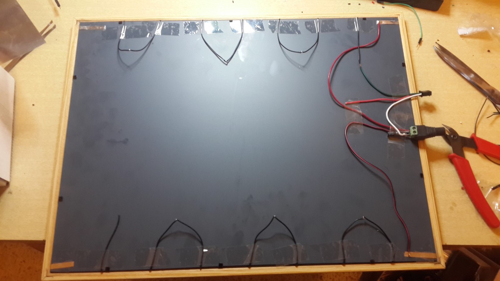
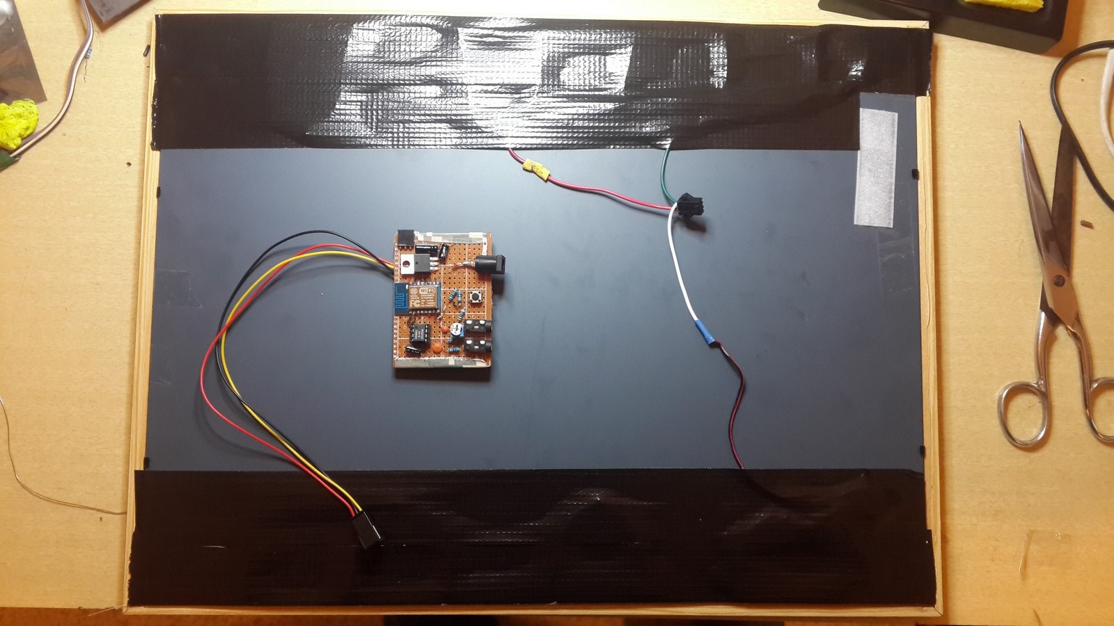
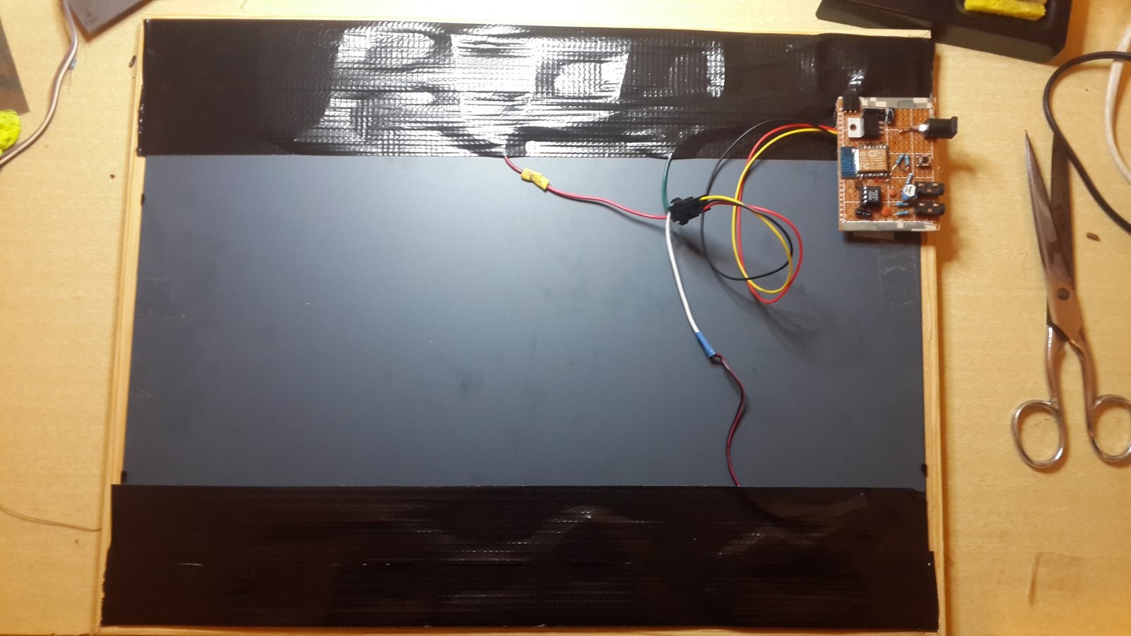
The next step was reconstructing the display. I cut 7 strips of 36 leds each, taped them to the mirror and connected the VCC, Ground and Data wires
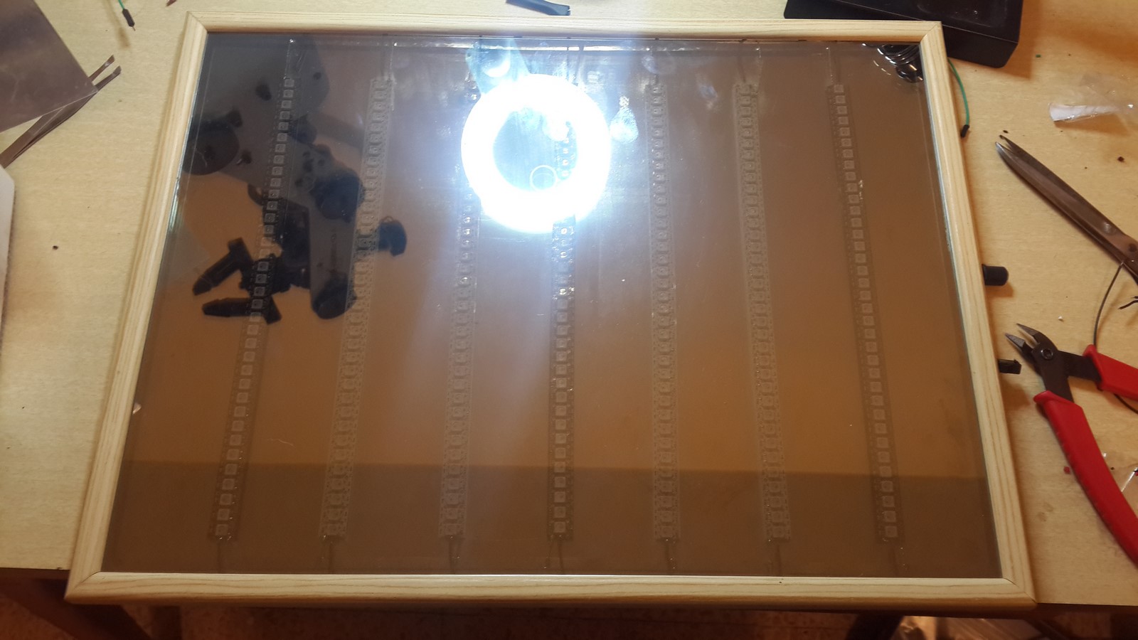
Next I took a picture frame of the same size (30cmX40cm), put inside the reflective glass, then the mirror, and finally tighten the frame from the back.
From the back, I connected the Data wires to eachother and the power wires to a power jack.
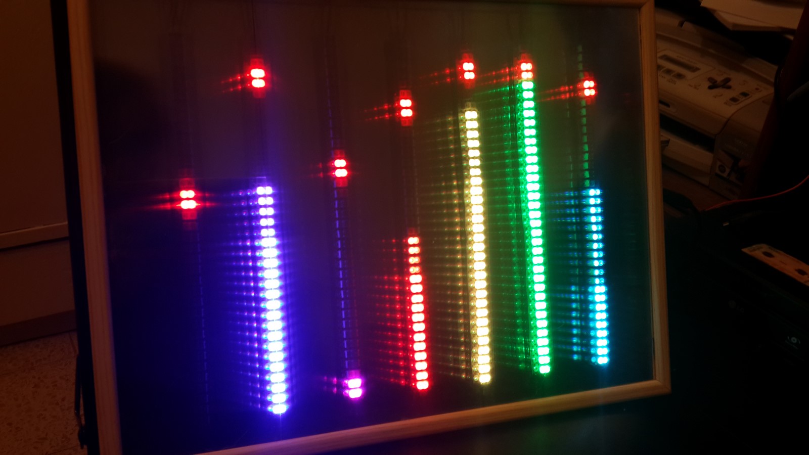
Tested the leds to see all is connected as it should:
Then, taped the last layer in the front to create the "infinity" effect:
Fianlly, I suggest putting some gaffer and velcro tape on the back of the PCB, cover the edges with hot glue
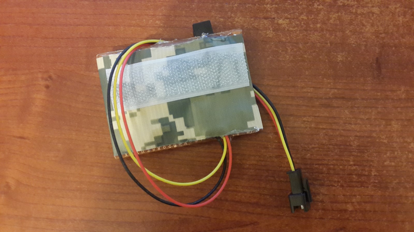
cover the rest of the wires on the back of the display with gaffer tape as well, and add velcro tape on the side for the PCB
Connect it all, and enjoy!
That's it, it works! All is left is to put some music, adjust the potentiometer/volume to the right value for a nice visualization and enjoy playing with the colors.
The project is not done yet! There some more things needed to be done! If something is not clear or you have more ideas on how to continue this project or just want to correct my English please comment below.
AA