Last summer a relative showed me his Tesla Model X do its impressive Sound & Light show. If you've never seen it, click here.
I decided to build my own - without the wheels - on a severely limited budget using only a $5 Raspberry Pi Zero.
If you're not a maker and have no interest in learning how it was done, click here to watch the video.
A bit of history
For the Christmas of 2016 I set about creating a sound and light system that was supposed to evolve into strings of coloured LEDs draped around the house. This was my proof of concept.
The System
I used Lightshowpi, a sophisticated application designed specifically for Sound & Light shows. This specific package is for Raspberry Pi (written largely in Python) and lets you choose your music to blast your neighbors with thumping lights.
For my prototype I used:
- A Raspberry Pi 3
- An eight-gang relay board
- 12 volt leds
- A USB speaker
I posted a little movie on my YouTube channel and I received a few comments - the most significant about the relays. Apparently mechanical relays won't last long when triggered dozens of times a minute. "Up to a week," was the general consensus.
That's why I didn't get past my 2016 prototype; I had nothing to substitute for the relays and Christmas had been and gone. The project was consigned to the "in progress" upper shelf until the next inclination took me.
A couple of years later, Elon Musk stepped into the equation.
The Parts
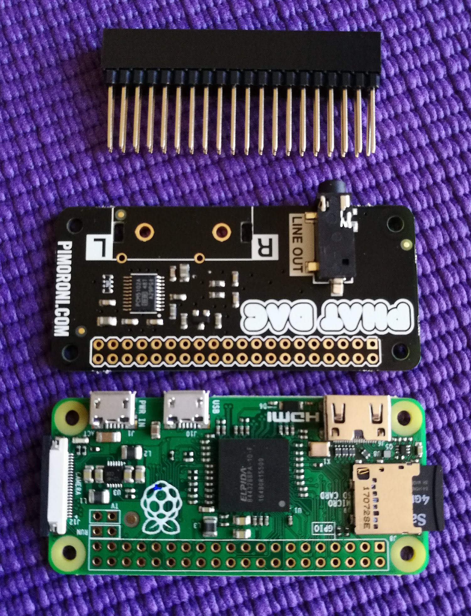
- Raspberry Pi zero - the cheapest version - without Wifi
- Pimoroni pHAT DAC - a digital-audio converter required for two purposes - 1) to gain access to the Pi Zero's audio output and 2) improve its native audio. (More about this below).
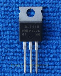
- Eight IRLZ44N MOSFETs - used to switch the 12v power to the LEDs. (More about this below.)
- Eight 12v LED strips acquired from Aliexpress. If the link is no longer active, search for "DC 12V 17cm 100% Waterproof Ultra Bright COB LED Daytime Running lights."
- A cable connector - (More about this below.)
- An amplified speaker.
Losing your Head
Before I delve into things, I need to point out that I did everything "headless," commanding my Pi remotely, not with an attached screen. These instructions reflect the experience. (I won't explain here how to operate the Pi remotely; that's covered in a million other places.)
Limitations of the RasPi Zero
As explained above, in my prototype I used a RasPi 3 but I knew I could probably run the system on a much cheaper Zero. If you choose to go this way, keep the following in mind:
You'll need to find a way to get the analog sound out. The RasPi 3 has four USB ports - one of which can be used for a sound card. The Zero has a single micro USB port so you'll need both a converter to get up to the standard USB size, and then a sound card.
If you're using the Zero's single USB port for the sound card, you can't use it for a USB WiFi dongle - that you might need for initial setup.
Initially I used a USB sound card on the Zero - but I wasn't happy with the result. I felt the Pi didn't have enough "juice" to run the card and do everything else I needed it to do. The sound was jumpy, unpleasant and weak.
That's when I began considering a DAC. It's a separate board that takes the Pi's analog sound through its GPIO pins and converts it to digital. There are several available for the Pi, but I wanted the simplest (and cheapest) for my project. That's when I came across the Pimoroni pHAT.
If you use the pHAT DAC, you'll need to acquire stacking pin headers that will give access to your RasPi pins even after you've installed the DAC.
Installing Lightshowpi
The Lightshowpi website provides clear instructions for installing the software. Here are some tips from my own experience to help you along the way:
- At first I wasn't clear if the Zero was "powerful enough" to run the application. Be assured, it can.
- My Pi is quite happy running everything on a 4gb SD card.
- I'd recommend using the "lite" version of Raspbian. It places less "demand" in your Pi and works well.
- Having said that, I had an unresolved problem getting "Stretch" (at the time of writing, the latest version of Raspbian) to work with LightshowPi and the DAC together. It does work on Stretch, just not with LightshowPi. In the end, and after many exchanges on the Pimoroni and lightshowpi forums, I gave up and went back to Jessie - which worked "out of the box". If you're using a USB sound card, you should be fine.
Overview of Lightshowpi
Lightshowpi allows you to place music on the Pi and play it while outputting to the computer's GPIO pins. Attached to your pins are "switches" that pulse rapidly, flashing your lights in time to the music. More about the "switches" below. The standard package includes eight channels, each responding to a different frequency of sound. (With a few alterations you can control many more than eight channels, but that's beyond the scope of this blog.)
The configuration of lightshowpi is contained in the file:
~/home/pi/lightshowpi/config/defaults.cfg
However, before you start fiddling with it, copy it to
~/home/pi/lightshowpi/config/overrides.cfg
and make your alterations there. This way, if lightshowpi updates, you retain your personal settings.
The above file is extremely well documented - and a bit daunting for the newcomer. It's only when you've read it carefully that you realize that only a few lines contain commands; the rest is an explanation of what's going on.
One curious thing I came across by accident. I felt my lights weren't "sensitive enough" to the frequencies of the music. This can be adjusted using the command:
custom_channel_frequencies
However, I found my own solution by mistake and I'm much more satisfied with the result. When defining my pins, I defined nine pins instead of eight and the effect was remarkable.
So what's with the switches?
For those new to small computer boards, here's the issue...
Such boards will only output up to 5 volts on their pins. So how can you use 5 volts to turn off and on mains current of 110v/220v?
There are several ways to do it.
As I explained above, in my prototype I used mechanical relays. These relays are basically switches that can be activated and deactivated by a 5-volt signal coming from the Pi's GPIO pins. The low voltage side is isolated from the high voltage terminals at the other end. At the "high voltage" end you can attach a mains current. (Don't overdo it. Many of the cheap relays from China purport to carry up to 10 amps. I'd be hesitant to exceed 3-4 amps.) This is where you can attach long strings of powerful Christmas lights for your garden.
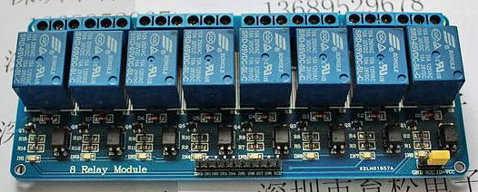
The problem with mechanical relays is that they wear out - especially if operated continuously and rapidly.
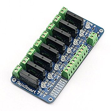
A solution is to use Solid State Relays - the same concept, but without the moving parts. They can operate much more quickly, don't wear out, and they're completely silent - unlike the mechanical relays that make rapid clicking noises (that personally, I find just as satisfying as the music itself!)
In the end, for my Tesla Sound & Light show I decided to keep everything portable. I wanted a single board with everything on it - that I could easily carry around. To do this, it would be easier to use bright, 12 volt LEDs instead of dangerous and complicated mains voltage.
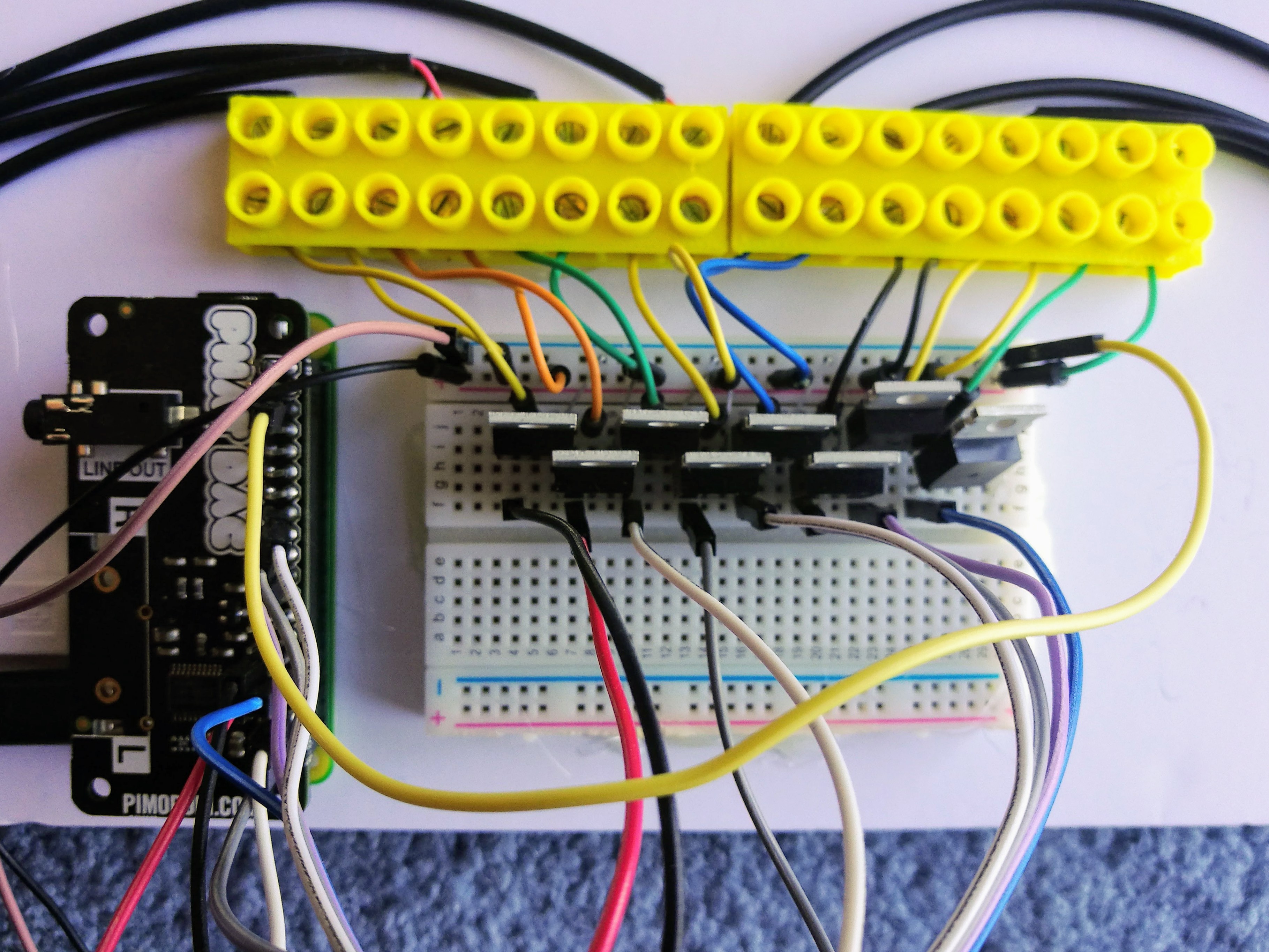
That's when I went for the MOSFETs - a solid-state switch similar to the Solid State Relay, but smaller, less obtrusive and perfect for this type of low voltage application. The IRLZ44N I used works well with the 5-volt output of the RasPi's GPIO pins.
 .
.
The MOSFET has the added advantage that it's not just ON or OFF. By varying the input voltage, the output varies too. So the lights can vary in intensity - as illustrated in the video at the end of this post.
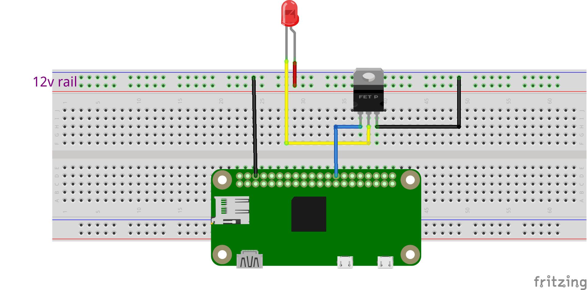
How to wire the MOSFET
Wiring the MOSFET is pretty simple. Here's a basic diagram with a single MOSFET. Just replicate the connections for each LED.
Two things to keep in mind:
- Make sure you define the correct Pi pin numbers in your overrides.cfg file in the lightshowpi configuration.
- Notice the LEDs run on the 12v rail. However, your RasPi GND should connect to the same rail, as illustrated. (Note, the LED in the diagram is for illustration only. It is not the LED I used in my build).
The Digital to Audio Converter (DAC)
By default, the Pi Zero outputs sound through its HDMI port. Unlike other RasPi versions, it has no analog audio socket. I tried using a USB soundcard but the sound was terrible. That's why I went for a DAC.
There are a few DACs for the Pi but I went for the pHAT from Pimoroni because:
- It was less than half the price of its nearest rival.
- It has good user reviews.
- It has the same form factor as the Zero.
- It has a line out stereo jack and space for RCA phono connectors
- It uses the same software control as HiFiBerry, a more expensive DAC.
- Pimornoni provides a one-line installer.
I spent many hours trying to work out why the pHAT would not work on Raspbian "Stretch" with Lighshowpi. In the end, I gave up and installed it on Jessie where it worked fine.
Volume Control
The pHAT DAC doesn't have a volume control and if you're not expecting it, when it assaults you at full volume it can blow your head off. Fortunately, there's a workaround to give it a software master volume. This is what worked for me.
Include in the file, /etc/asound.conf:
pcm.!default  {
   type plug
   slave.pcm "speakerphat"
}
   ctl.!default {
   type hw card 0
}
pcm.speakerphat {
   type softvol
   slave.pcm "plughw:0"
   control.name "PCM"
   control.card 0
}
Once you've made these changes, reboot, then type into your command line:
alsamixer
This should allow you to adjust the volume with your arrow keys.
Building and Wiring the Project
My aim was to have an entire Sound & Light system with the following characteristics:
- It would be on a single portable board that could easily be moved around.
- The system needed to be light to make it easy to hang on a wall.
- The board should contain all of the components to avoid trailing wires across the floor. This meant putting eight lights, the controlling RasPi Zero, the sound card, and the switching mechanism all on the same board.
- Only two components were not on the board:
- The power supply.
- The amplified speaker.
The Board
For my initial build, I bought a Foamcore board from a craft store - but now that I have things set up and working, I'll move it over to a thin sheet of plywood.
Powering the Pi from 12 volts
At the time of publication, I have not yet implemented this, but will do so when my parts arrive on their slow boat from China.
As described above, the LEDs required a 12-volt power supply. The Pi requires just 5 volts. Of course, I don't want to use a separate supply for each, so I'm weighing up two alternatives.
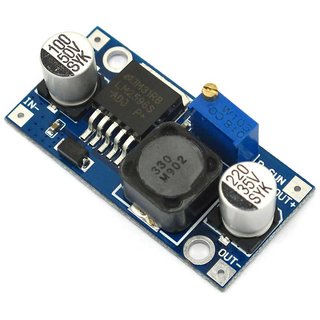
I could either use a 12-volt power source and step down to 5v for the Pi using a DC-DC Step-Down Buck Converter Module.
Alternatively, I could use a 5 volt supply and step up to 12v for the LEDs.
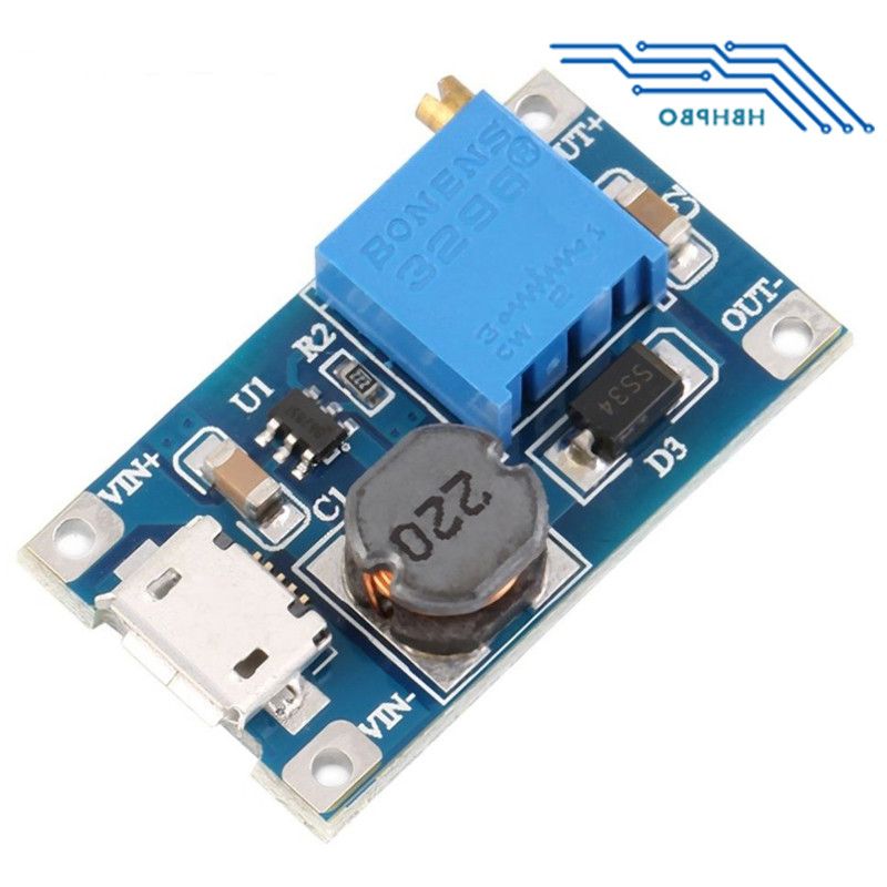
I've decided initially to try the latter for a couple of reasons:
- My 12v wall-wart power supply it ugly and heavy. By using a small 5v Micro-USB (3 amp) charger, I could greatly reduce the bulk.
- I'm only driving eight short LED strips, which together don't draw much current. I believe a small step-up board should be able to handle their demand.
- My step-up board (pictured) has a micro-USB socket into which I can plug an existing cable. From the same end I can splice off 5v to the RasPi, and from the other end, take 12v for the LEDs.
Connecting the cables
I wanted to find a neat little cable connector for my LEDs but didn't have something on hand for all 16 wires. My local hardware store only had electrician's screw-in connectors.
I decided to improvise a little with my own 3D-printed alternative that was slightly less "industrial" and much narrower than the original.
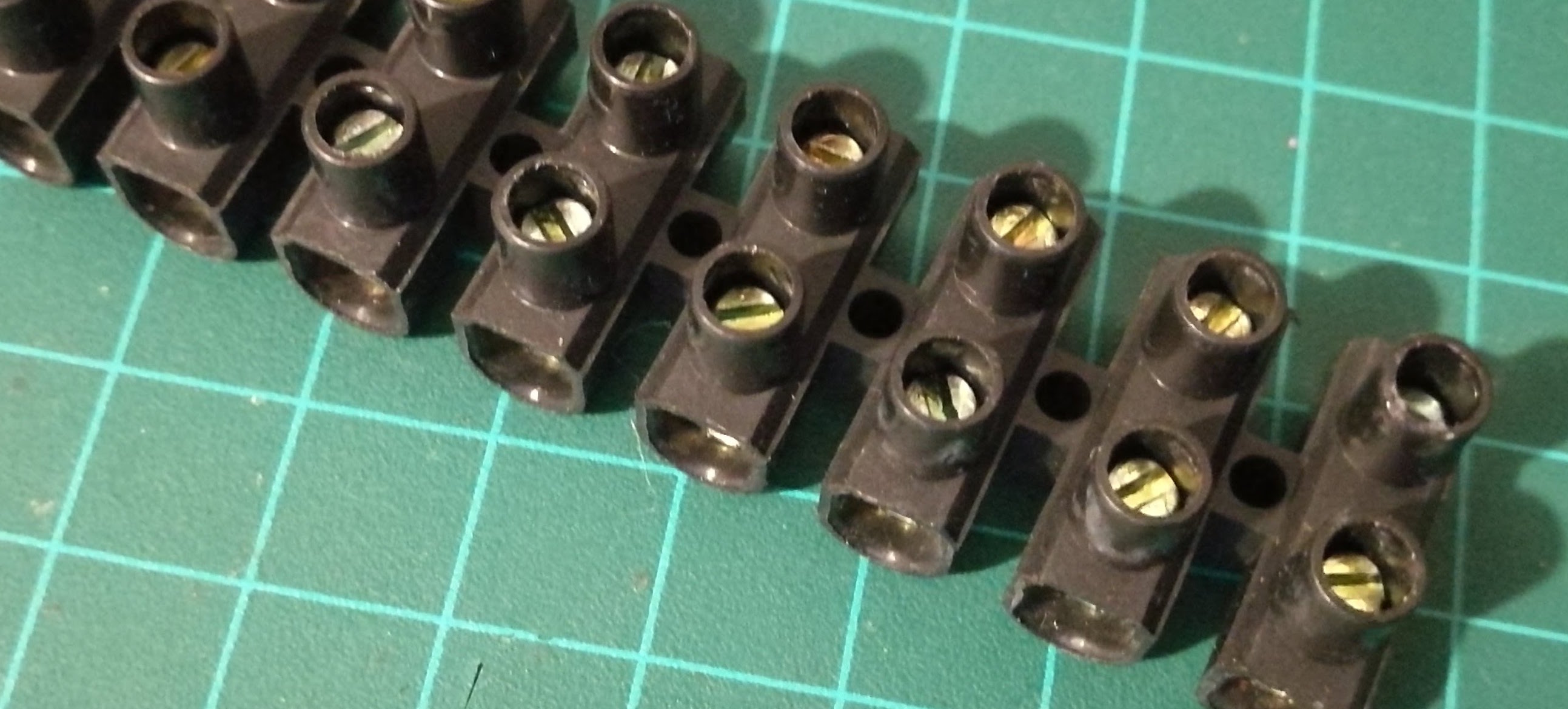
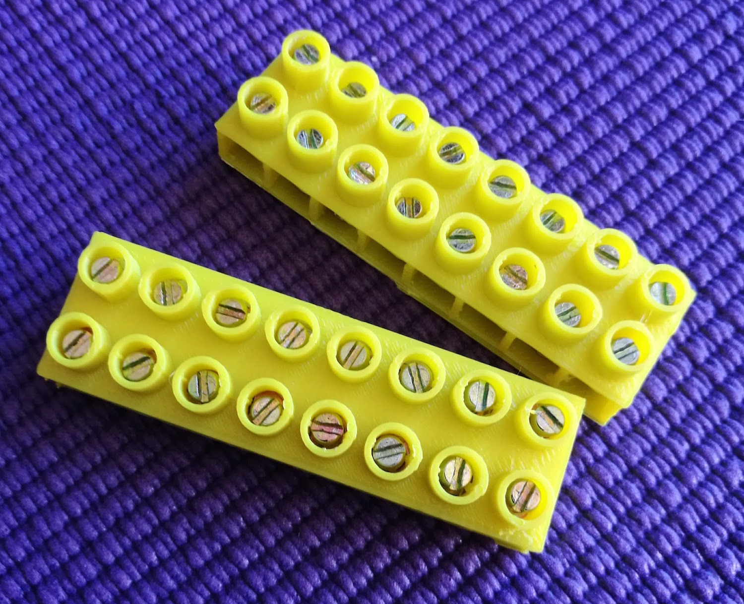 I could have created a common +12v for eight of the LEDs, but it was just as easy to plug them into the 12-volt rail.
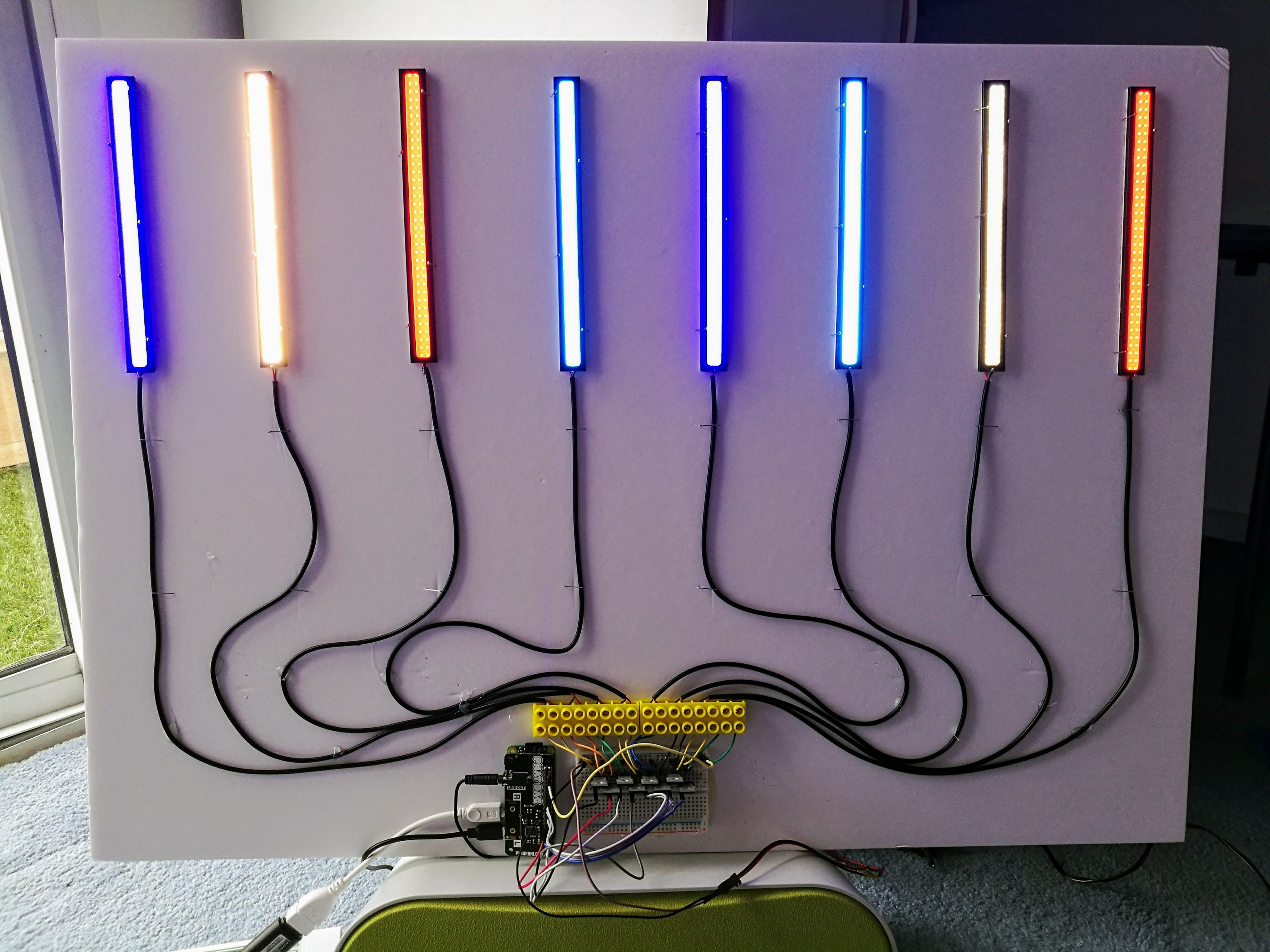
It's not very elegant but these connections take up very little room at the base of the display and give it a nice "geeky" look.
The (almost) Finished Item
Getting Music onto the Pi
Although the show operates without a WiFi connection, it's useful to have while setting things up. This provides an easy way to transfer music files into your Pi.
My preferred way of moving files backward and forward is through Filezilla, a free, very powerful and easy-to-use FTP client. Just type in the Pi's IP address and you're connected in seconds. Moving files from your main computer to the Pi is just a simple drag and drop.
 .
.
A Few Features of LightshowPi
I've not explored it thoroughly, but a couple of features of LightshowPi have come to my attention.
- Creating a playlist is quite fidgety if you try to do it manually. Included in the ~/lightshowpi/tools directory is a python script that does it for you. (I admit that I've never got it to work. The script compiles the playlist but I'm still struggling to get the Pi to play it!)
cd ~/lightshowpi/tools
sudo python playlist_generator.py
- There's also a basic web interface that can be implemented with:
cd ~/lightshowpi/web/microweb
sudo python web_controls.py
Then point your browser URL at the IP address of your RasPi.