UPDATE (Nov 24th 2019) - If you like this post, there's a part 2 to this post with some more upgrades.
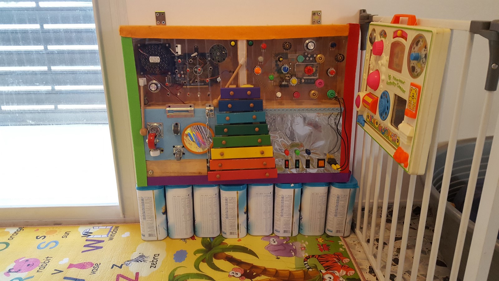
In this post I'll describe a project that I'm still upgrading from time to time, but has already been in use for the last three months. About 15 months ago my first daughter was born, and between all the congrats I received there was also a congrats from my blog's friend Michael, who added something like "see you back on the blog in 20 years" with a wink. So I decided to find a way to involve my two loves, my daughter and my hobby, and build a cool toy for her, while also documenting it on the blog (Take that Michael :) ). The toy is a "busy board", which means a board with a lot of unrelated stuff, some can be turned, some can be pushed, some can be rolled. Here's the toy on the first day I gave it to my daughter, exactly on her 1st birthday:
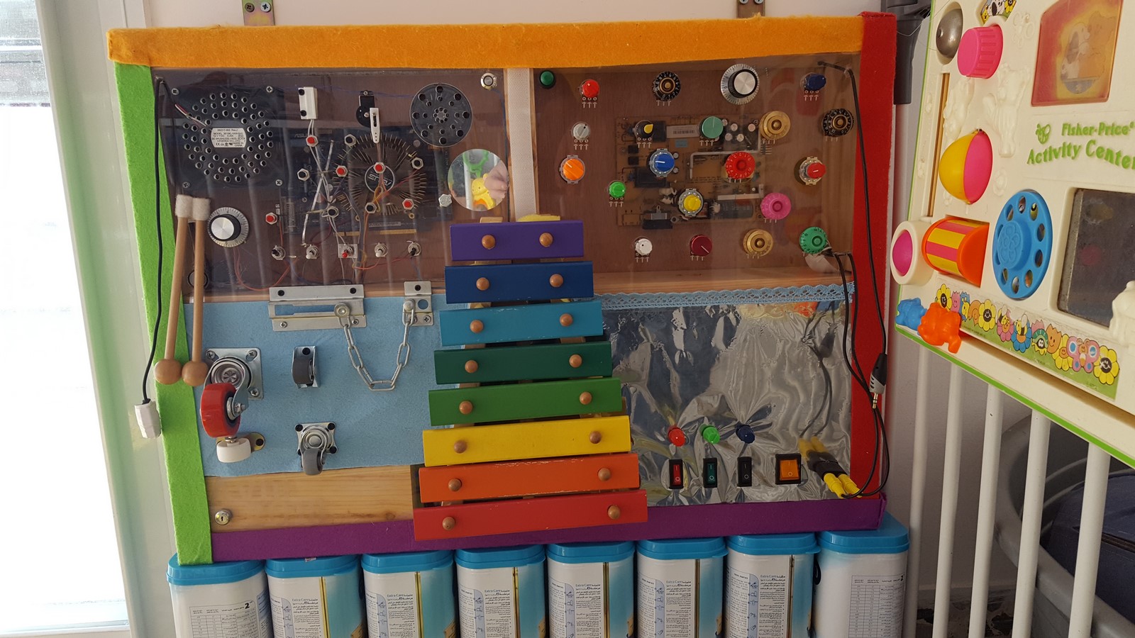
What we have inside?
- Xylophone
- Wheels
- Locks
- Cables and connectors
- Computer fan
- Speaker
- Mirror
- Knobs
- Buttons
- switches
- Key switch
- Servo motor
- Magnetic sensor and a magnet
- Pressure sensor
- LEDs (strips, matrices) and 7-segment board
As I mentioned, the project is still updated from time to time. Here's a video of the first upgrade of the upper left corner (Turn up the volume):
What you saw in the video:
- On-Off switch with a key (Not used by the toddler).
- Buttons which make sound when pressed, sound files can be switched to a second set with one of the switches.
- Knob controls volume.
- Computer fan can be turned on with a switch or a magnet.
- Pressure sensor controls a servo motor.
- Other switches control RGB light, different combinations creates different colors.
- In addition, every interaction with everything mentioned above involve also LED lights for the atmosphere.
Important Note: If you plan to build one of those, always think about your child's safety! This is not a toy from the store with ISO standards so make sure you think about everything - small parts, electricity, sharp edges etc. I've added some tips for safety at the end of the post
That's it for the TL;DR! Now let's focus on the building process.
Planning
When you have kids everything goes slower than you plan (Except them growing up...). I started planning this project more than 6 months ago, gathering a lot of leftovers I had from former projects, and at the same time, ordering a lot of cool knobs from Tayda Electronics. The good part about not having much free time is that suddenly it seems as if mail packages from east-Asia arrive much faster!
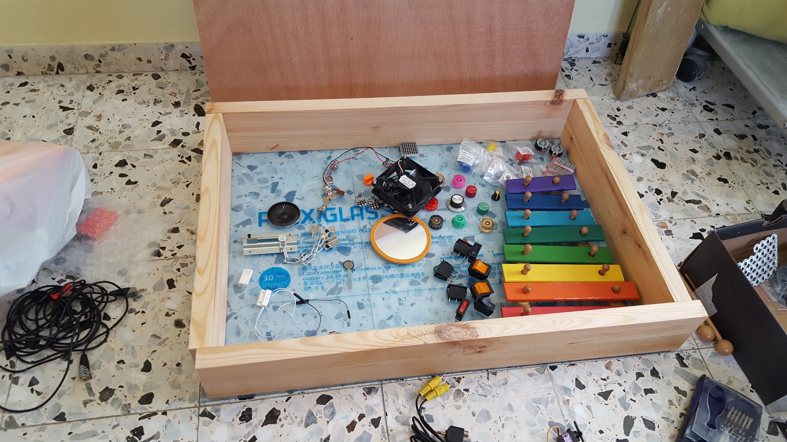
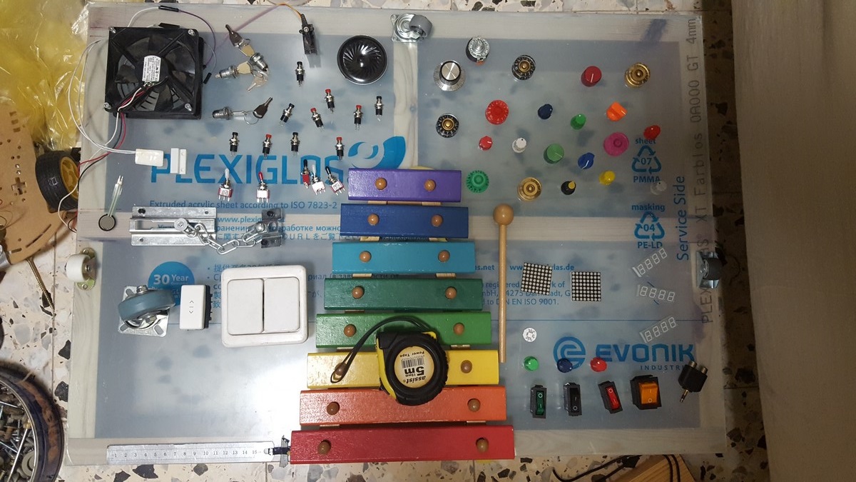
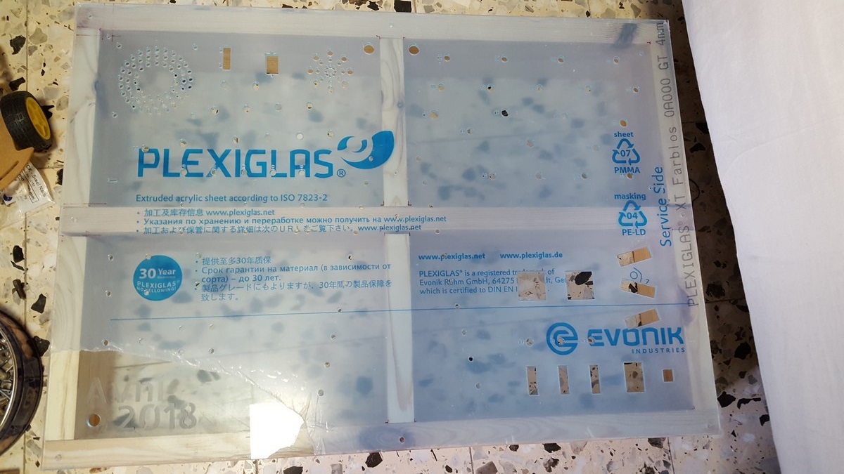
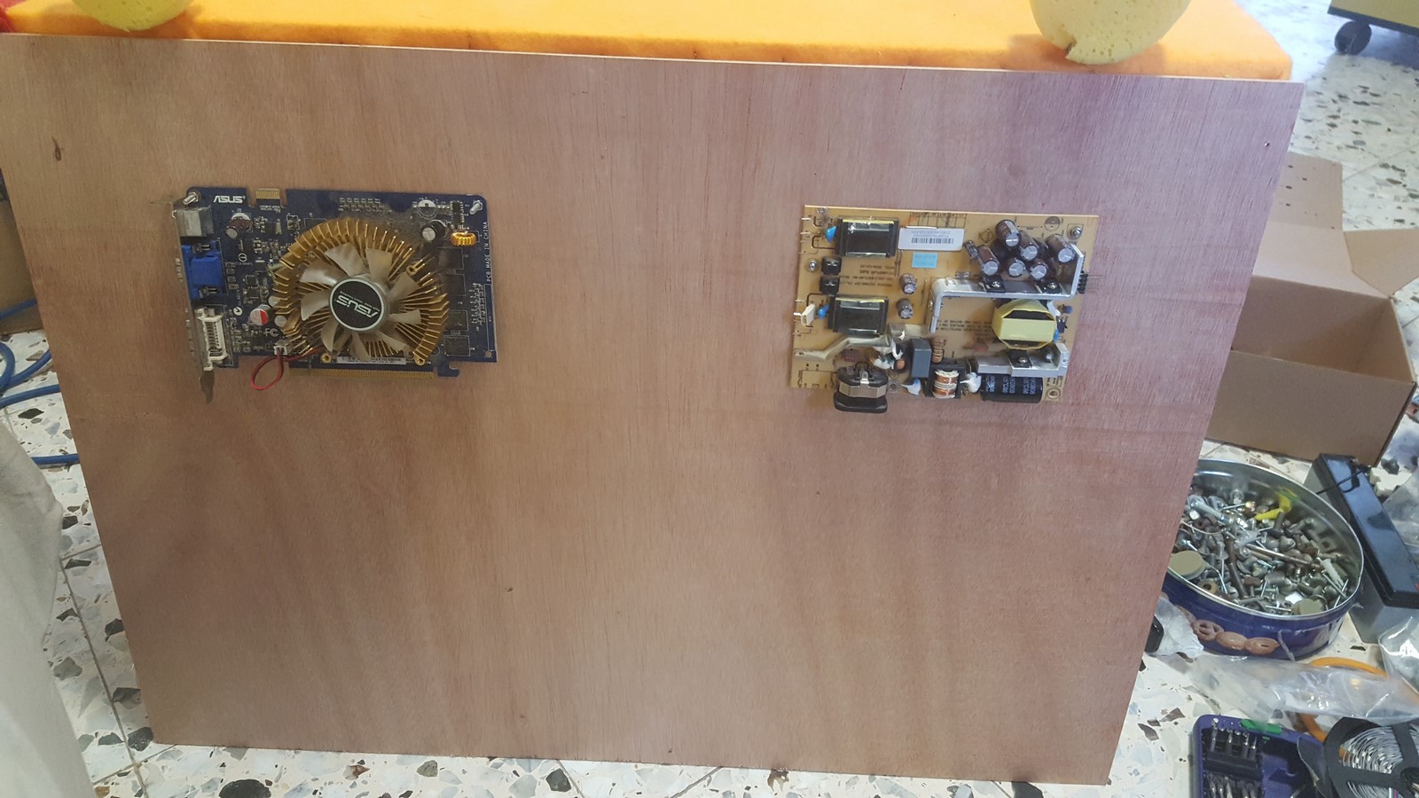
The frontal part of the board was a 4mm Plexiglas ("perspex") board, 500mm X 700mm. I had it from a former project, but it can be purchased from any store/workshop/factory which deals with these materials. The first thing I did was to put all the parts on top of the board and to start organizing them.
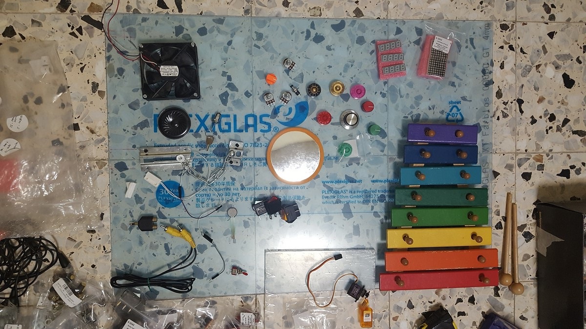
Notice that it looks very different from the final result, but it was a good place to start.
Next I made a small sketch for the laser-cutter, for some of the parts, and laser-cut it using a very small board just to test the accuracy and robustness of the cuts and the board. The results were very good.
Building the Frame
Since my skills in everything related to carpentry are not very high (but I'm working on getting better...) there might be a better way to do what I'll describe here.
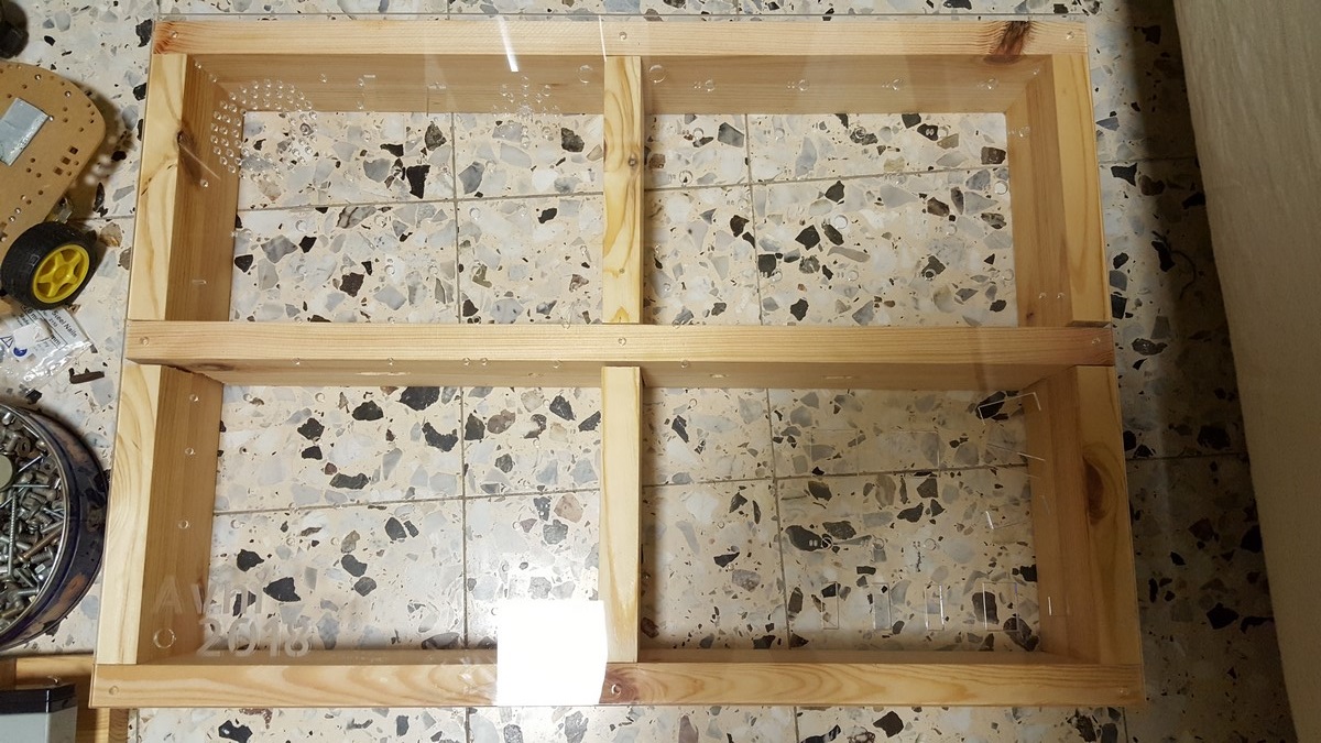
I wanted the frame to be stable, and also prevent the Plexiglas board from breaking, thus decided to make a frame with a "plus" in the middle to make it more robust. I went to the carpentry with my design and got all the wooden parts. I had a small mistake in the planning, and thought the wood would be 30mm thick when in fact it was 27.5mm thick. So the board was eventually 5mm longer than the frame, but that wasn't a big deal.
These are the outer frame parts:
The inner parts had to be cut a bit at the center so they will hold each other in the best way.
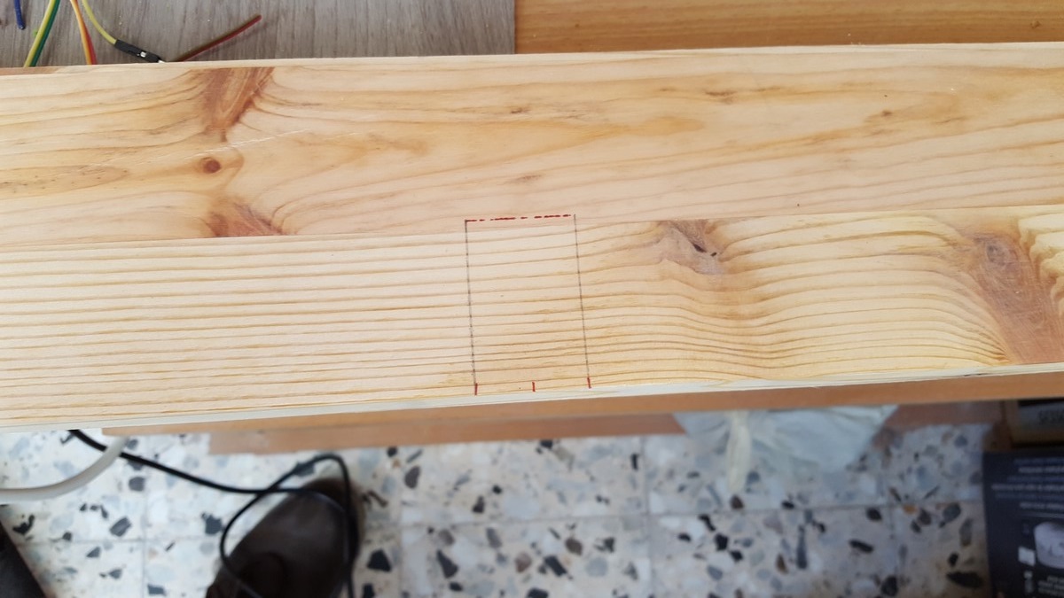
I used a jigsaw, looking back I probably should have used a manual saw since it was very hard to make exact cuts with the jigsaw. Finally the frame was ready:
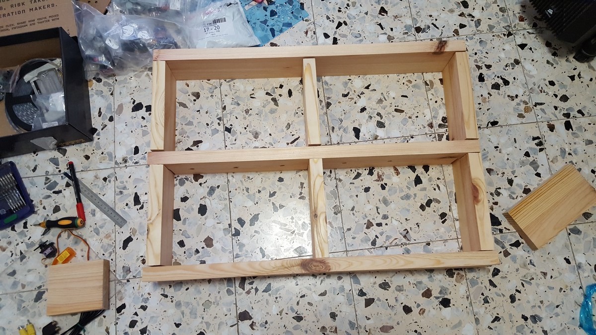
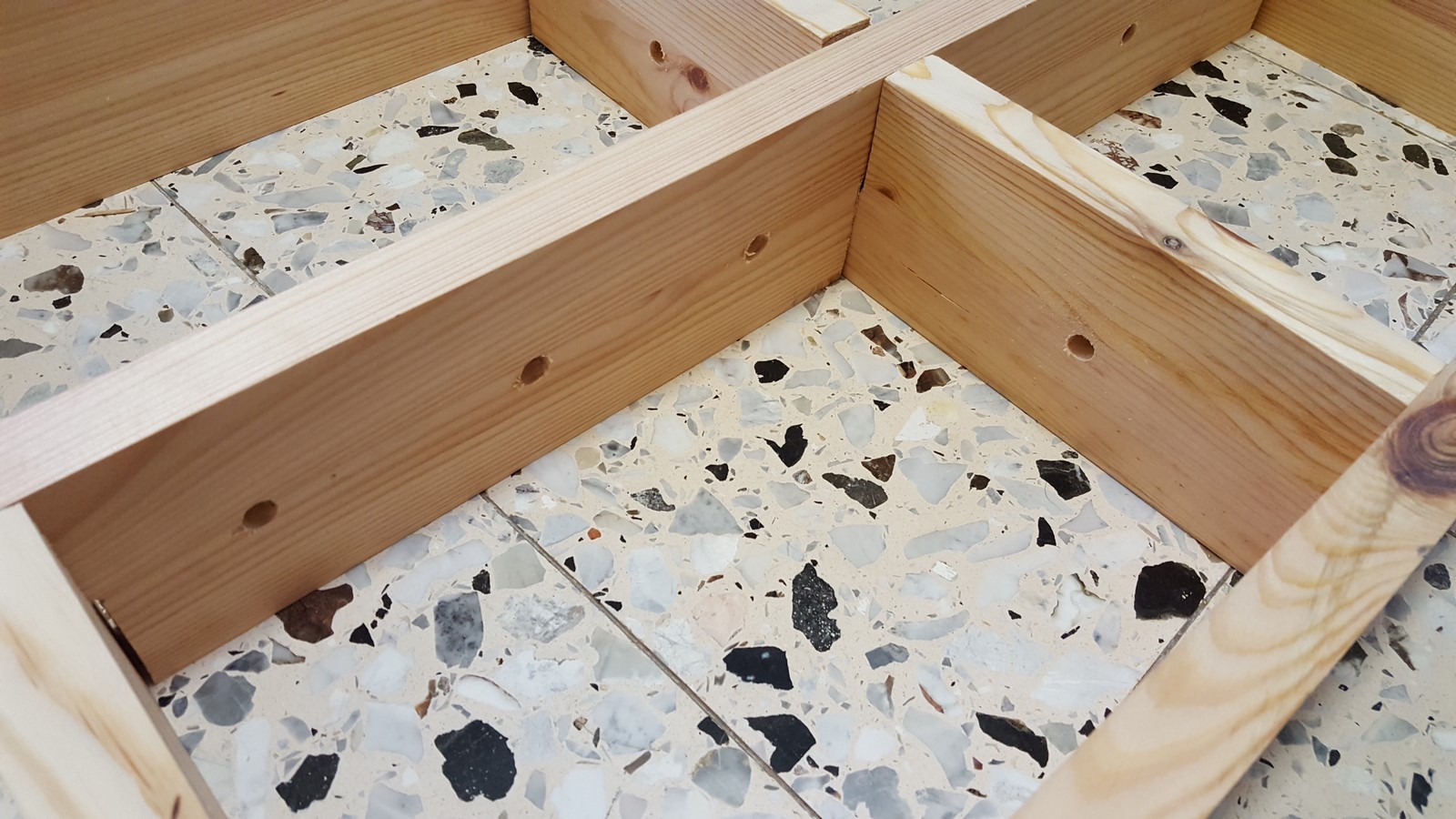
I also drilled a few holes in all the inner parts, thinking ahead about passing cables between the different quarters.
Laser-Cutter - From Designing to Cutting and Engraving
After the frame was ready I put back the Plexiglas board and went back to the planning stage, putting once again all the parts on top of the board and organizing them. This time it looks a bit more like the final design.
Then I measured all the lengths from the outer and inner frame, and started designing using Onshape. Even if you don't have an account, you can use my design following this link
This was the first time I ever used this website for design and it was really easy to use. Few tips I can share for first timers:
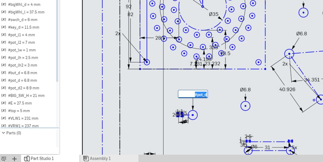
- There's an option of drawing lines which are just visible but not part of the design (Construction geometry). These are great in order to draw all the frame borderlines so you'll know where to draw the parts for cutting. In the next sketch you can see the actual work area on Onshape, where the black lines are visible only and the blue lines are the actual design.
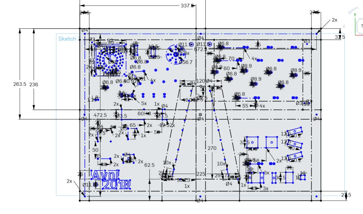
- Use variables! I set almost all the patterns' sizes as variables, and defined the variables on the variable list. That way, even if the size of a certain knob is a diameter of 7mm but when testing and cutting it actually become 7.2mm, I can easily change the variable size to 6.8mm and it'll change the sizes of all the designs I made for these certain knobs. See an example on the next sketch, where I defined #pot_d for potentiometer diameter and the program reads it as 6.8mm
When I was done, I exported the sketch to a DXF file and opened it with CoralDraw on a computer which sends jobs to the laser cutter. Since big Plexiglas boards are not cheap, I first took a cardboard box, flattened it and put it in the machine instead of the Plexiglas board (Using much lower laser power).
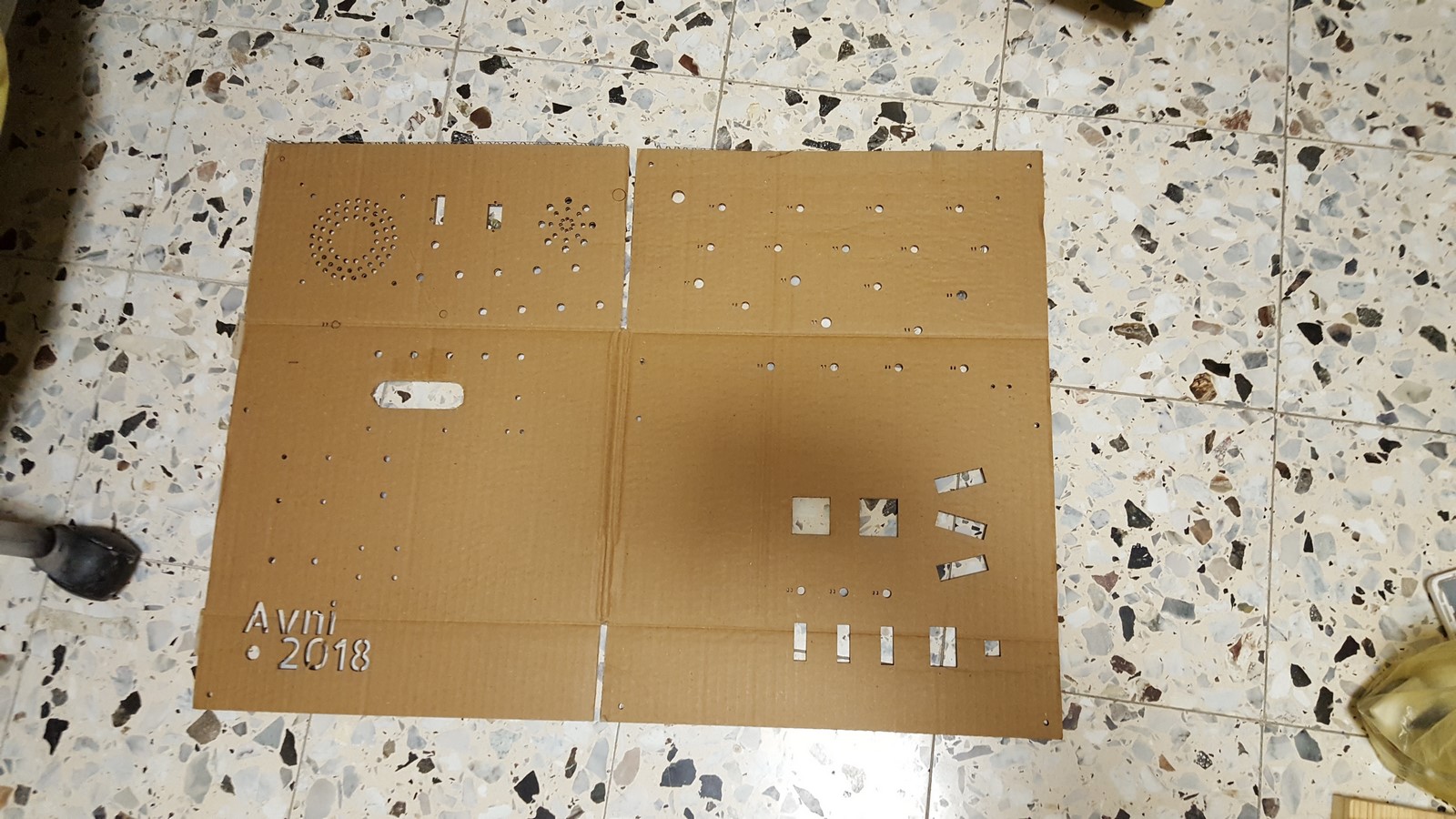
The cutting was really fast! about 1-2 minutes and I could analyze the results. Using the cardboard helped me realize some holes where too small or too big, and also the text I wrote was cut when I wanted it to be engraved.
I adjusted the numbers and configs and made a few more tests on cardboard and Plexiglas leftovers until I was happy with the results.
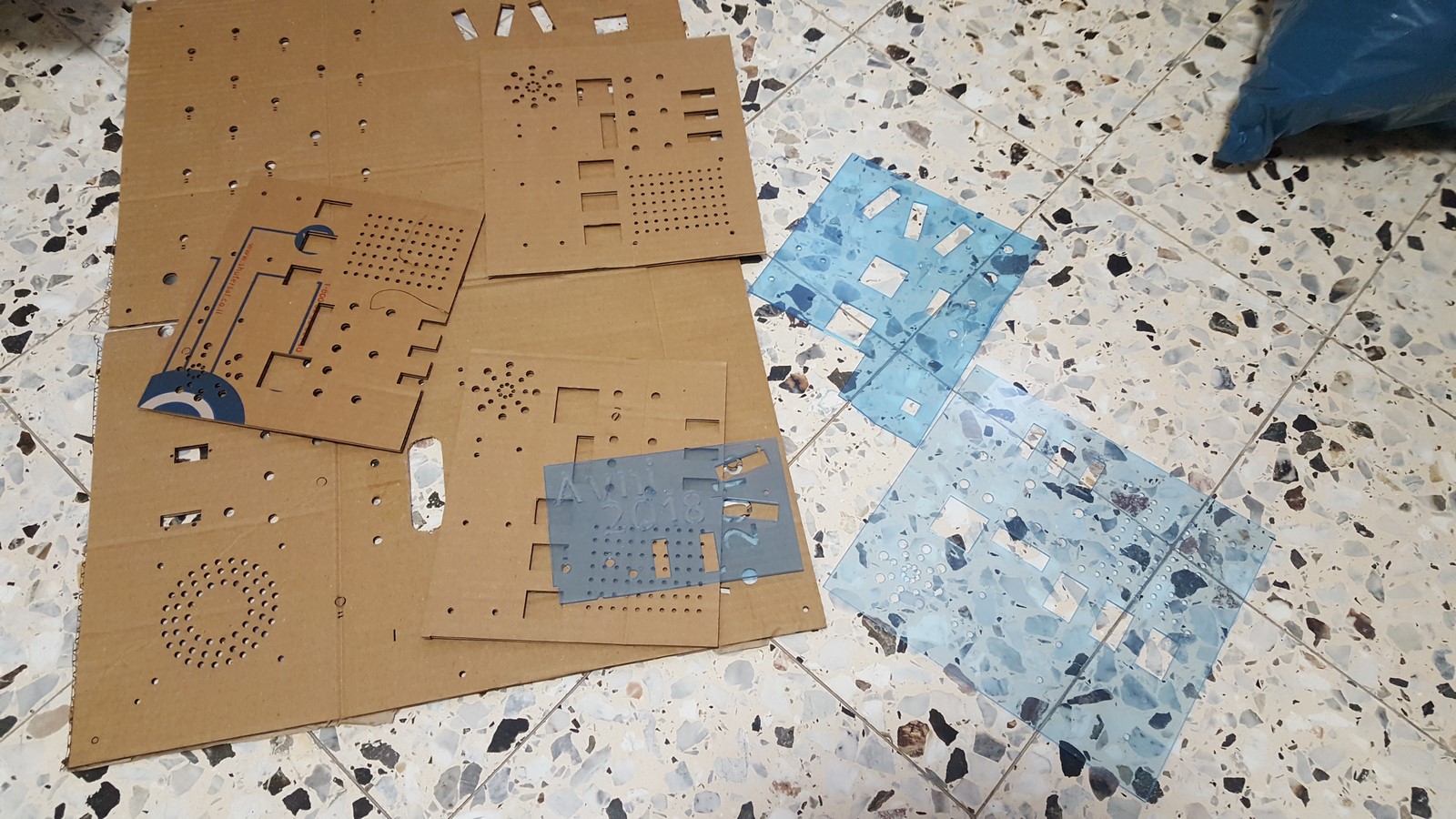
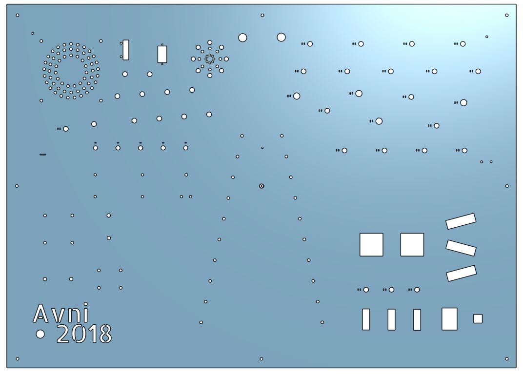
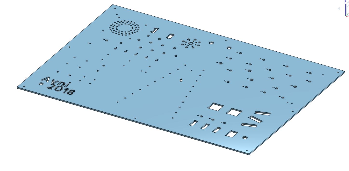
Finally I was ready for the real deal. From my experience, it is best not to remove the Plexiglas sticker when cutting, and remove it when engraving, so here is the final sketch I've used and how it looked like when the cutting was done:
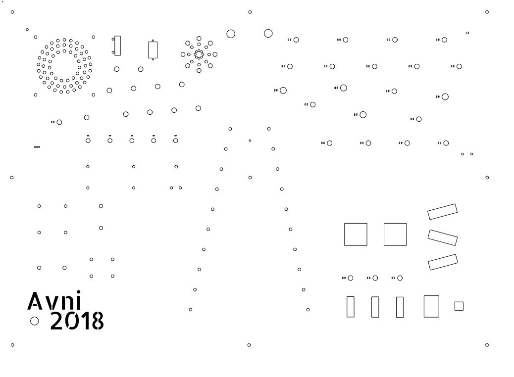
and after removing the sticker:
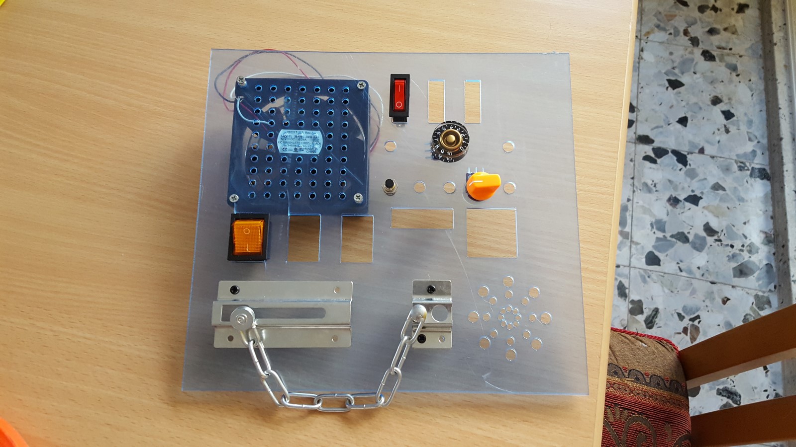
Assembling
The next step was assembling all the parts. A photo and some notes about that:
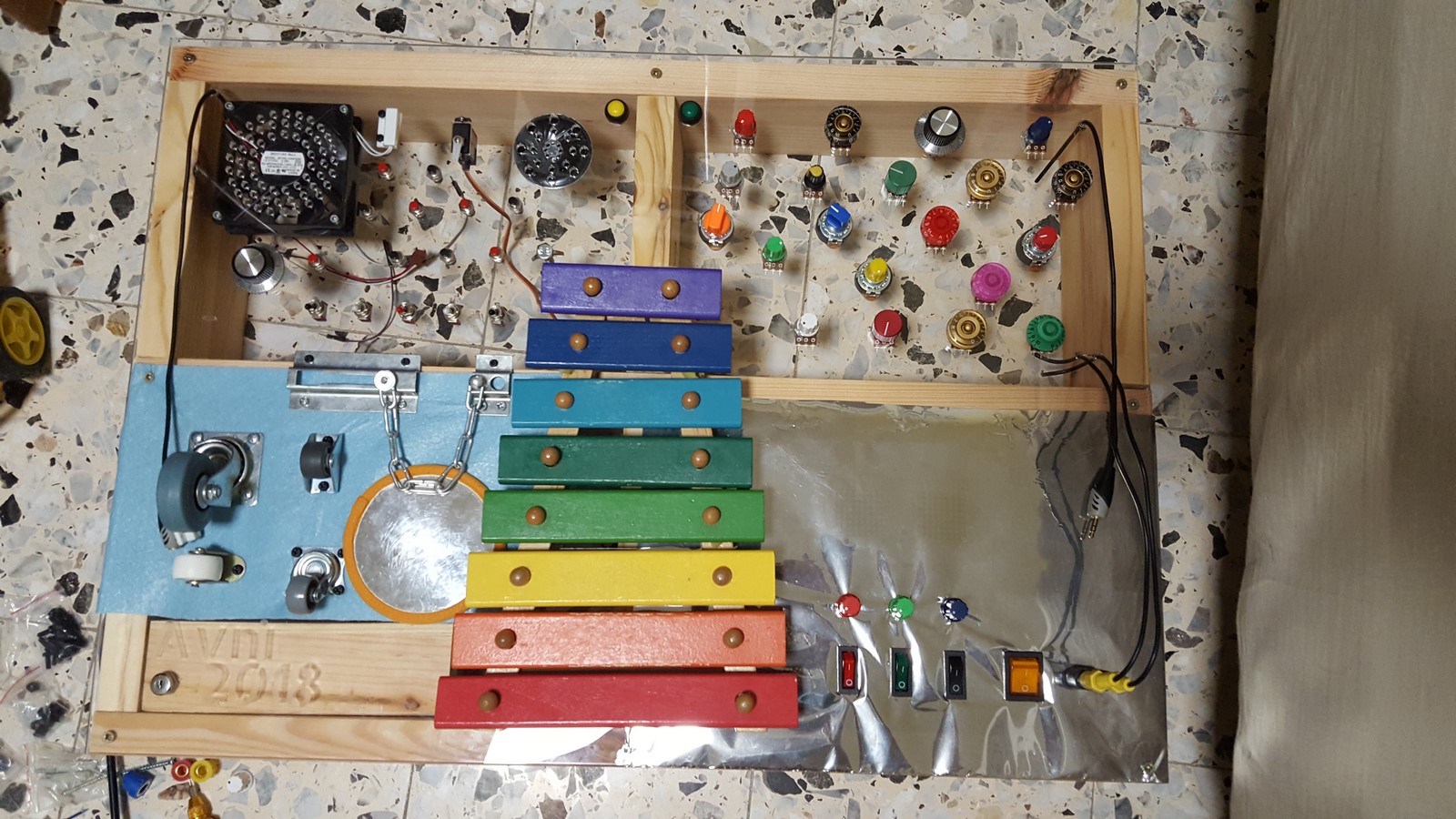
- Bottom right - I glued a reflective mirror cover on the Plexiglas, so that it would look like a mirror but when the LEDs behind the cover would work they would still be seen.
- Bottom left - I covered the board with some felt fabric, since behind that I was going to put most of the electronics.
- Beside using screws to make the parts permanent, I used glue from the inner part of the box to make sure they would definitely not move.
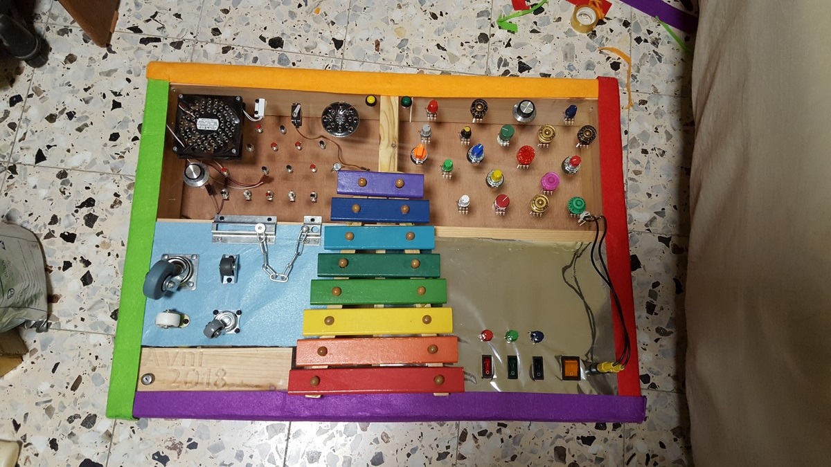
Next, I glued and stapled some more felt fabrics around the box so it would have less sharp edges and be more colorful.
Just for swag, I added some old PCBs to the back cover of the box:
And finally, added some metal angles (Don't know the right term in English) to the top of the box so I could hang it on the wall, and that's it! The assembly was finished.
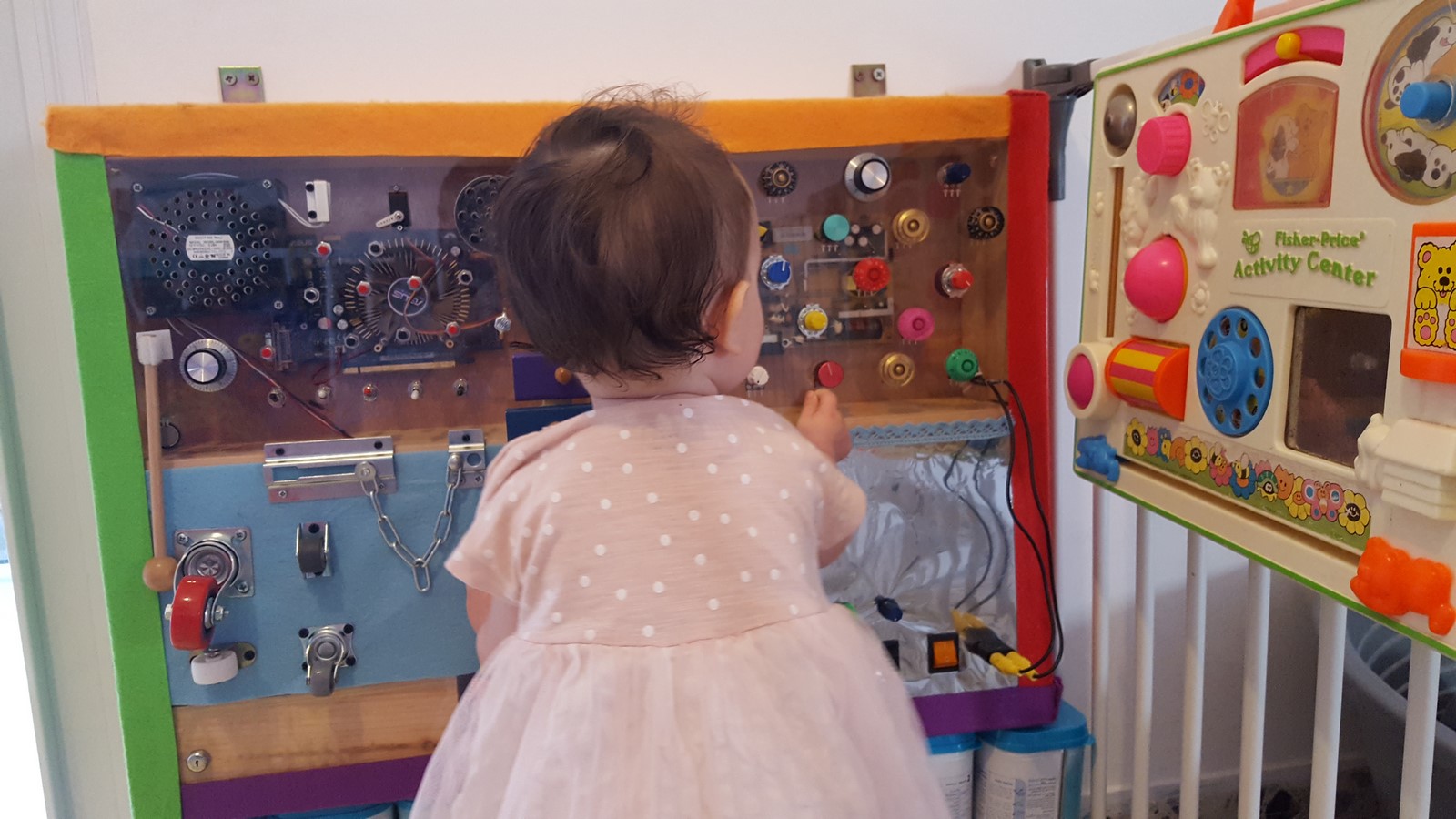
At that point I gave it to my daughter. Even though it didn't produce any sounds or lights, it was still interesting enough for her age. After two months of playing with it, I decided it was time to take it off the wall and give it a nice first upgrade (more to come)
Upgrade #1 - Hardware and Software Top-Left quarter
(tl;dr - code is here)
This upgrade was about bringing to life the top left corner which had already consisted of the next items:
- Computer fan
- Knob
- Pressure sensor
- 10 X Buttons
- 5 X switches
- Magnetic sensor
- Servo motor
- Speaker
The functionalities I made are mentioned at the beginning of this post.
Hardware
First, I had to create a power supply. Using an outlet wasn't an option since I didn't want high voltage involved. Instead I used a 12V rechargeable Lead Acid battery. I needed 12V for the fan, and 5V for everything else, so I came up with this power supply circuit:
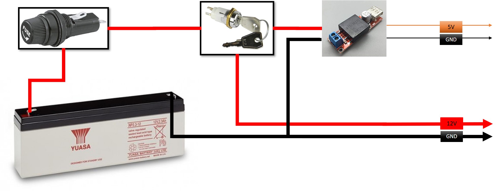
The power from the battery goes through a 4A fuse - a safety feature to protect from short-circuit. Then it goes through a key switch, which is necessary to turn the power on/off. Then it goes to the circuit, and also through a step-down module which outputs 5V to the circuit. You might be asking yourself why I used an external step down from 12V to 5V, when the Arduino has one on its PCB? The answer is that many of the items were powered by the 5V supply and I was afraid I'll need much more current than the internal step-down can supply, leading to it being damaged.
Eventually, the entire circuit when everything was on, took about 300mA, and when ideal took about 20-30mA. The Battery power marked as 2.3AH, can give a full day of intensive play or several weeks of average play before the battery needs to be charged.
The hardware itself includes the next items and connections (Sorry for the bad sketch but there were just too many items):
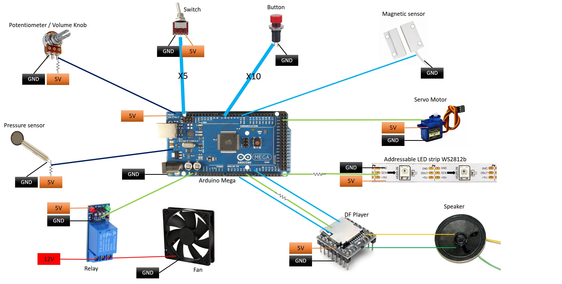
Some notes about the sketch:
- The exact pin connections on the arduino are not mentioned in this sketch - and can be found in the code.
- The light-green lines are connections to the items from the GPIOs on the Arduino, where the GPIOs are defined as OUTPUT pins.
- The light-blue lines are connections from the items to the digital GPIOs on the Arduino, where the GPIOs are defined as INPUT pins.
- The dark-blue lines are connections from the items to the analog GPIOs on the Arduino.
- The INPUT pins of the buttons and the magnetic sensor have also an internal PULL-UP resistor (from the pins to 5V).
- The pressure sensor is actually a resistor which changes its resistance when touched, thus it's circuit is actually a voltage divider. Same for the potentiometer (knob/volume control).
- The switches, buttons and magnetic sensor can change the GPIO state between high and low or 5V / GND.
- The servo motor is a standard servo with a PWM signal.
- The LED strip is an addressable WS2812B strip.
- The relay is a standard relay module, which controls the 12V of the fan.
- The lines to/from the DF player are TX, RX and a "busy" pin, which states if the player is playing a sound or not.
- The DF Player is a really cool module which is actually a board for a MP3 player, it can be controlled by an Arduino (but also without it), play mp3/wav files from an SD card to an external speaker, skip between files, change volume etc. I found it very handy for kids' toys since you can easily remove the card and change the sounds if you get annoyed by them (Which often happens with kids' toys).
- Half of the MP3 files on the SD card are sounds I recorded myself (Me, my wife, my daughter), and the other half are animals' sounds which were taken from freesound.org, a great website for free sounds.
- The RX pin on the DF player is connected with a resistor. This is actually very important because the player works with a different voltage. I tried using it without the resistor and it didn't work.
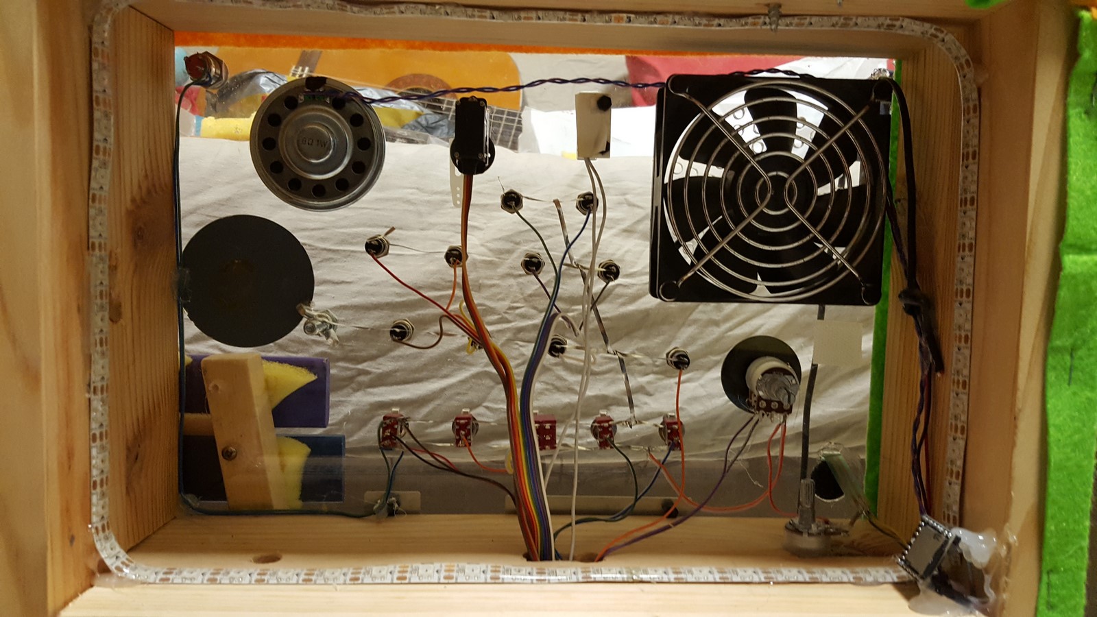
Here are two more photos of the top and bottom of the toy. This time from behind, after I finished soldering everything, followed by some more notes:
Top:
Bottom:
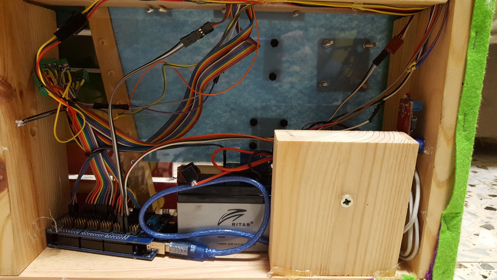
- The power supply and the Arduino are hidden at the bottom.
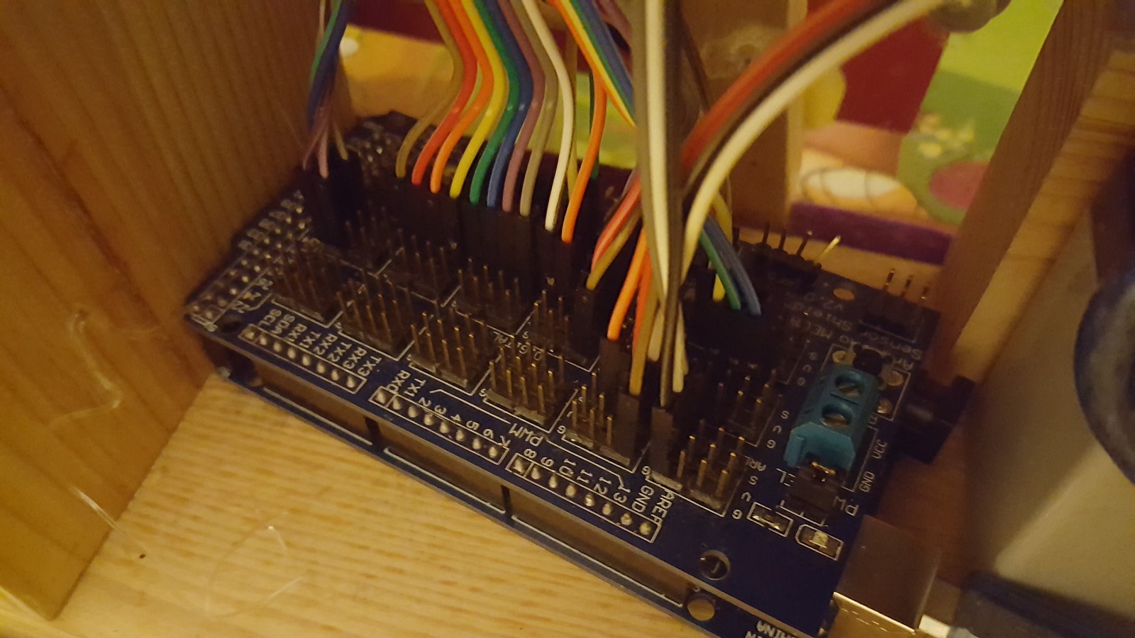
- I used a shield on the Arduino Mega, mainly because I had it lying around, but it made the connections much easier and more arranged.
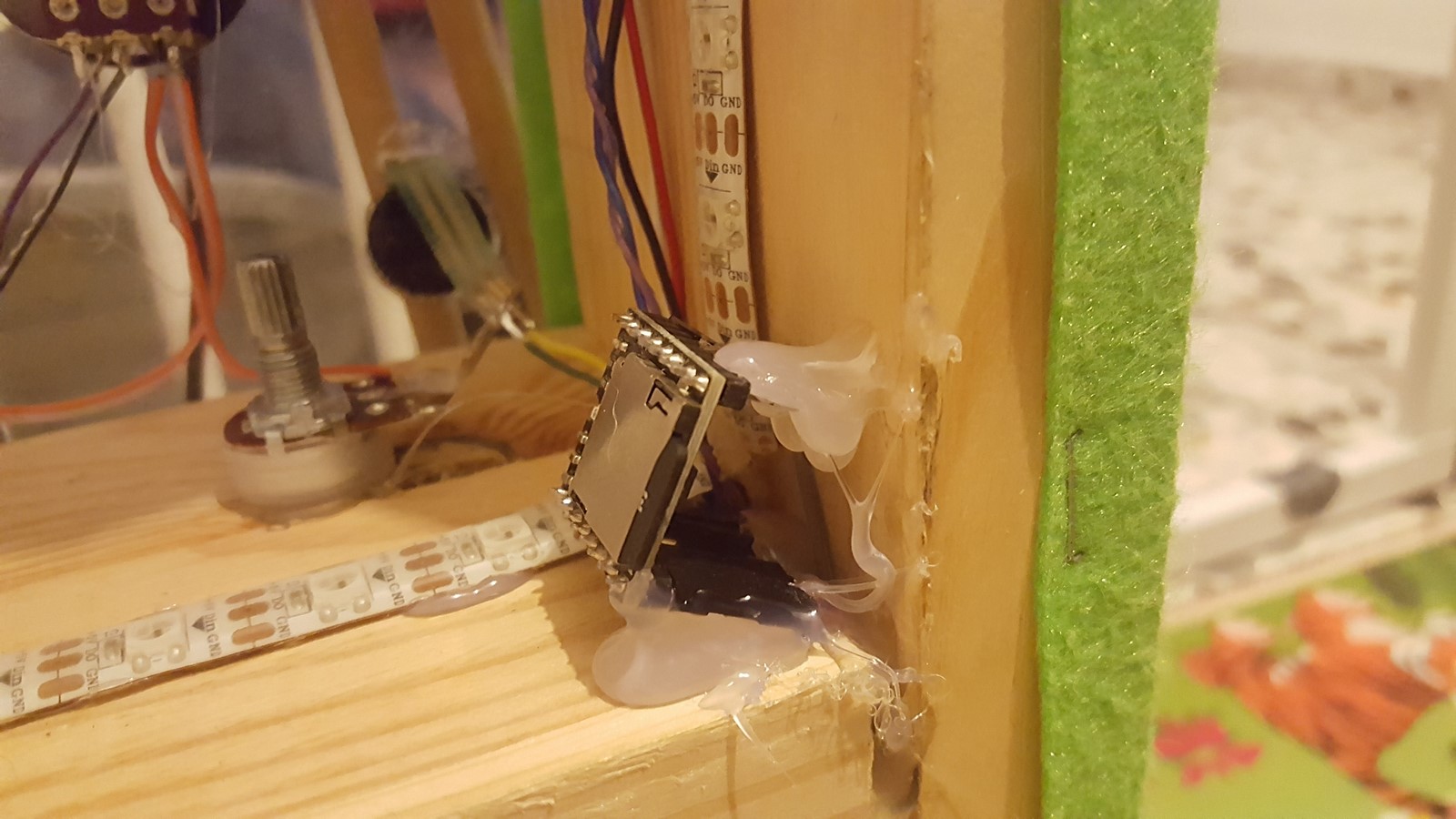
- The DF player was placed on the right side of the top part. I placed it there so it'll be easy to remove the SD card without disassembling the entire box.
- The addressable LEDs are glued all around the top part, but I used only some of them. It was just more comfortable that way.
- All the buttons and switches have GND / 5V thick line using a tabbing wire I still own since my solar panel project.
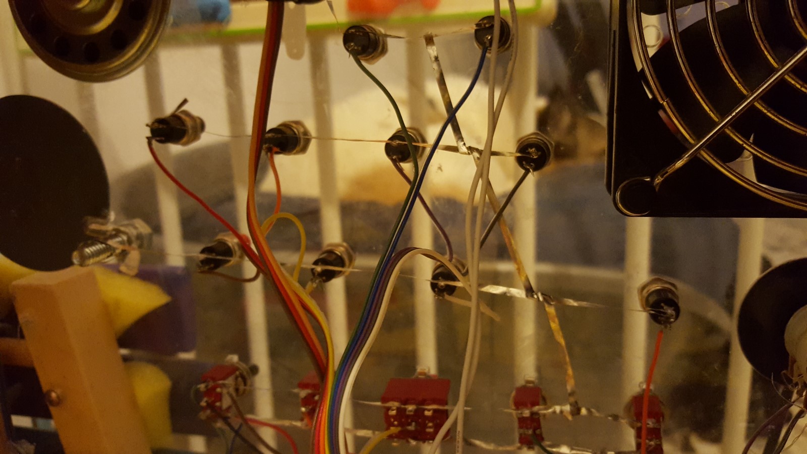
- The wires look like a mess but they are actually very organized. It is easy to get lost using so much wires so it is important to create some kind of order when you solder them.
Software
The code to this circuit can be found on Github and it consists of two files.
define.h - In this file I defined all the pins connections, so if you build something similar and want to use the code, all the pin numbers are there.
TopLeftCode.ino - The code Basically plays an infinite loop which checks and executes the following functions (Can be found in the code comments as well):
- Check pressure sensor value and update LEDs and servo motor if needed.
- MP3 Player - If a button was pressed - Play certain sound and turn on LEDs. If the knob was turned - Change volume.
- MP3 Player - Check Serial (For DEBUG only) - If there's a problem with the player it will send a text serial with info about the problem.
- Switch #1 - change MP3 files set (triggered by the 10 buttons) from 0-9 to 10-19 and vise versa.
- Power on/off the fan using magnetic sensor or switch #2.
- Switches #3/4/5 - Change LEDs colors.
- Check for ideal usage - If nothing was pressed for 20 minutes turn off everything and go to sleep (To make battery last longer).
Safety Tips For Conclusion
As I mentioned throughout this post, if you are planning to build something for your child (Or any child), think hard about everything bad that can happen, and take safety measures in advance. Eventually you will work hard (and enjoy throughout the process) in order to make your child happy, and if something bad will happen the entire effort won't be worth it. I'm sure anyone who reads this post can comment and add some more tips which I'll be happy to hear and implement. Here are my two cents about the subject:
- No high voltage! Yes, it is comfortable you won't need to change batteries every now and then but if you somehow messed up something on the way it can lead to a disaster. Even if you didn't mess up, the child might break some of the toy at some point.
- No small parts! Toddlers can put them in their mouth and choke. Regarding any small parts you have to use, make sure they are on the inner section of your project so they are unreachable. If they are on the outside, glue them with a strong glue and after it dries use your maximum force to check if they can be pulled out.
- Make everything extra robust - Add an extra screw if needed, even two, more glue ect. Try to break things with reasonable power and make sure you can't.
- No sharp edges - If you use wood or Plexiglas you probably have some sharp edges. Try to smooth them or cover them with smoother materials.
- Don't use toxic materials - At least not on the outer section.
AA